80
GRINDER MIXER ADJUSTMENTS
Figure 153 - Hydraulic Swing Adjustment (Shields
Removed For Clarity).
1. Loosen the four hydraulic motor bolts and
remove the #60 chain.
2. Wrap the #60 chain completely around the 55
tooth sprocket. Inspect the chain, matching the
sprocket teeth in the two areas where the
sprocket is split. If the rollers on the chain do
not seat into the root of the sprocket teeth,
loosen the 10 bolts that hold the sprocket to the
upper ring; holding the chain across the split
areas, re-tighten the bolts so the chain properly
seats into the sprocket teeth.
3. Re-tighten the hydraulic motor bolts then check
the alignment of the sprocket. If the sprocket is
not aligned properly, loosen the set screws on
the 10 tooth sprocket and re-align.
4. Reinstall #60 chain and tension. Reinstall
Shield.
5. Adjust spring tension to be sure auger will slip
if it hits something solid (See Figure 153). If it
doesn’t slip, damage to discharge could occur.
H
YDRAULIC
S
WING
S
PEED
A
DJUSTMENT
The speed of the discharge auger swing can be
controlled by adjusting the flow control valves at the
swing motor (See Figure 154). These valves are
preset at the factory to be open 1.5 turns. When
changing the swing speed be sure to adjust both
valves equally. Different valve settings will cause
excessive back pressure at the motor that my
cause shaft seal failure.
To adjust the flow control valves, loosen the jam nut
behind the knob. Turn the knob clockwise for lower
flow or counter-clockwise for higher flow. Mark the
knobs so they can both be adjusted equally.
Tighten the jam nut after adjustments are finished
and check discharge auger swing for proper
operation.
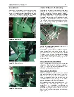
Figure 154 - Hydraulic Swing Flow Control Valves.
L
IFT
A
SSIST
S
PRING
A
DJUSTMENT
The lift assist spring may loose tension after
excessive usage. It is important to keep proper
tension on the spring, this spring helps ease raising
and lowering the discharge auger. Adjust the spring
tension by removing bolt in hole and moving to the
hole shown (See Figure 155). Additional tension
needed with discharge extensions.
Figure 155 - Lift Assist Spring Adjustment Bolts
Hydraulic
Discharge
Chains
’
Adjustment (6105H Models Only)
Hydraulic Discharge models contain three 9.6 CID
hydraulic motors (See Figure 156, Figure 157, and
Figure 158).
The upper discharge motor is directly coupled to the
auger shaft using four set screws (See Figure 156).
The middle discharge uses a #60 chain and
sprockets. The tension is maintained using a
positive stop style tensioner. Loosen jam nut
followed by tightening or loosening bolt for proper
chain tension (See Figure 157).
Lower discharge motor uses a #40 chain,
sprockets, and wood block idler. Position wood
Summary of Contents for CATTLEMAXX 6105
Page 7: ...TABLE OF CONTENTS 5 ...
Page 14: ...12 INTRODUCTION Figure 5a Safety Decals ...
Page 22: ...20 PREPAIRING THE GINDER MIXER FOR OPERATION Figure 15 PTO Support ...
Page 27: ...OPERATION OF GRINDER MIXER 25 cleaned out Keep all bystanders away from the machine ...
Page 42: ...40 LUBRICATION Figure 70 Hammermill engaging pin shields removed for clarity ...
Page 49: ...SERVICE 47 Figure 96 Belt Removal Shields Removed For Clarity B C ...
Page 78: ...76 OPERATION OF CATTLEMAXX Figure 143 Hopper Inspection Window ...


