38
GRINDER MIXER ADJUSTMENTS
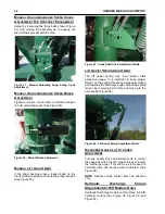
Figure 63 - Repositioning Unloading Auger.
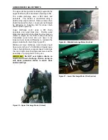
Figure 64 - Repositioning Unloading Auger.
STEP 4
– (See Figure 64) Disconnect the hydraulic
hoses from the cylinder. Remove the cylinder and
lower the cylinder mount from the lift lever and
vertical cylinder mount arm.
Re-attach the cylinder on the other side as shown.
(See Figure 64) Re-route the hydraulic hoses and
connect to the cylinder. Move the saddle to the
opposite side of the mixing tank. Lower the
unloading auger and rotate the hood so it faces
downward.
W
HEEL
B
EARINGS
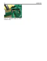
Raise the frame and make sure it is blocked
securely so the wheels may turn freely (make sure
the opposite wheel is also blocked securely). To
tighten the wheel bearing, remove the hub cap.
Remove the cotter pin from the slotted nut and
tighten the slotted nut while rotating the wheel.
Loosen or back-off the nut to the nearest slot, insert
and spread the cotter pin.
There should be a slight drag on the bearing
following the adjustment. Replace the hub cap.
(See Figure 65)
Figure 65 - Wheel Bearing Adjustment.
Summary of Contents for CATTLEMAXX 6105
Page 7: ...TABLE OF CONTENTS 5 ...
Page 14: ...12 INTRODUCTION Figure 5a Safety Decals ...
Page 22: ...20 PREPAIRING THE GINDER MIXER FOR OPERATION Figure 15 PTO Support ...
Page 27: ...OPERATION OF GRINDER MIXER 25 cleaned out Keep all bystanders away from the machine ...
Page 42: ...40 LUBRICATION Figure 70 Hammermill engaging pin shields removed for clarity ...
Page 49: ...SERVICE 47 Figure 96 Belt Removal Shields Removed For Clarity B C ...
Page 78: ...76 OPERATION OF CATTLEMAXX Figure 143 Hopper Inspection Window ...


