


28
OPERATION OF GRINDER MIXER
U
NLOADING
C
LUTCH
D
RIVE
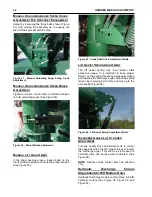
Starting at an idle, move the clutch handle ahead
and down to engage the augers. (See Figure 29)
Gradually increase speed to at least 2/3 throttle.
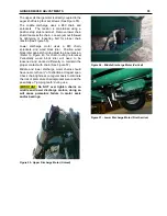
Open the unloading door. The eccentric may be
used to hold the door open. (See Figure 30) When
the tank is unloaded, reverse the procedure.
If equipped with optional electronic actuators,
engage the appropriate function. Make sure clutch
is fully engaged at the idle speed.
If equipped with optional hydraulic discharge
(6105H models), clutch is NOT installed.
NOTE:
If unloading in more than one location, close
the discharge door and empty the auger before
transporting the mixer.
Figure 29 - Unloading Clutch Operation.
Figure 30 - Unloading Door (A - Eccentric Lock).
Hydraulic Discharge (6105H Models
Only)
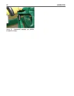
Connect two hydraulic discharge hoses to desired
hydraulic circuit on tractor. Hoses come installed
with Pioneer™ style male quick connectors from
factory (See Figure 31).
Slowly engage the hydraulic discharge with tractor.
Gradually increase speed to at least 2/3 throttle to
reduce the risk of bogging machine down or
potentially plugging an auger. Open the unloading
door slowly. The eccentric may be used to hold the
door open (See Figure 30).
When the tank is unloaded, reverse the procedure.
Always make sure that discharge is empty before
transporting mixer.
Figure 31 - Hydraulic Quick Connector
F
OLDING
A
UGER
E
XTENSION
Optional extensions for the unloading auger include
a 3 to 6 feet folding or bolt-on extension. (See
Figure 32) For discharge heights of the optional
extensions. (See Figure 33)
If the grinder mixer is equipped with a folding auger
extension, make sure the outer auger drive cog is
properly engaged and the extension tube is locked
before engaging the unloading clutch.
Figure 32 - Folding Auger Extension.
(6’ Extension
shown)
Summary of Contents for CATTLEMAXX 6105
Page 7: ...TABLE OF CONTENTS 5 ...
Page 14: ...12 INTRODUCTION Figure 5a Safety Decals ...
Page 22: ...20 PREPAIRING THE GINDER MIXER FOR OPERATION Figure 15 PTO Support ...
Page 27: ...OPERATION OF GRINDER MIXER 25 cleaned out Keep all bystanders away from the machine ...
Page 42: ...40 LUBRICATION Figure 70 Hammermill engaging pin shields removed for clarity ...
Page 49: ...SERVICE 47 Figure 96 Belt Removal Shields Removed For Clarity B C ...
Page 78: ...76 OPERATION OF CATTLEMAXX Figure 143 Hopper Inspection Window ...


