1
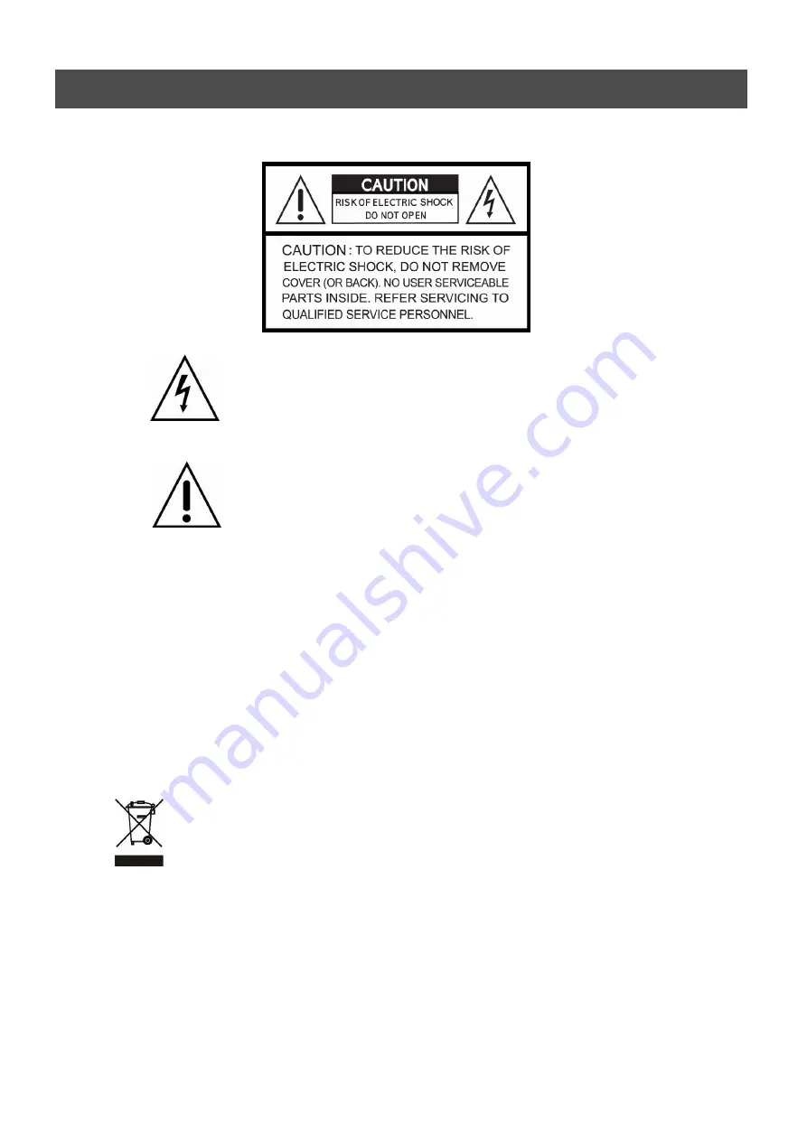
WARNING
This symbol is intended to alert the user to the presence of unprotected
“Dangerous voltage" within the product's enclosure that may be strong
enough to cause a risk of electric shock.
This symbol is intended to alert the user to the presence of
important operating and maintenance (servicing)
instructions in the literature accompanying the appliance.
WARNING
TO REDUCE THE RISK OF FIRE OR ELECTRIC SHOCK, DO NOT EXPOSE THIS
APPLIANCE TO RAIN OR MOISTURE.
NOTE:
This equipment has been tested and found to comply with the limits for a class
digital device, pursuant to part 15 of the FCC Rules. These limits are designed to provide
reasonable protection against harmful interference when the equipment is operated in a
commercial environment. This equipment generates, uses, and can radiate radio frequency
energy and, if not installed and used in accordance with the instruction manual, may cause
harmful interference to radio communications. Operation of this equipment in a residential
area is likely to cause harmful interference in which case the user will be required to correct
the interference at his own expense.
Disposal of Old Electical & Electronic Equipment
(Applicable in the European Union and other European countries with separate
collection systems)
This symbol on the product or on its packaging indicates that this product shall not be treated as
household waste. Instead it shall be handed over to the applicable collection point for the recycling
of electrical and electronic equipment. By ensuring this product is disposed of correctly, you will
help prevent potential negative consequences for the environment and human health, which could
otherwise be caused by inappropriate waste handling of this product. The recycling of materials will
help to conserve natural resources. For more detailed information about recycling of this product,
please contact your local city office , your household waste disposal service or the shop where you
purchased the product.
Summary of Contents for ANX-16480
Page 9: ...9 LOCATION AND CONTROL Chapter 3 Location and Control 3 1 FRONT PANEL CONTROLS 3 8...
Page 12: ...USER S MANUAL 12 INSTALLATION Chapter 4 Installation 4 1 TOTAL CONNECTION LAY OUT...
Page 41: ...USER S MANUAL 41 OPERATION You can click the below keys on the MENU screen with a mouse...
Page 91: ...91 HDD INSTALLATION PROCESS Chapter 9 256 Camera Integration system Block Diagram...


