22
Setting Internal Jumpers
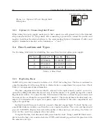
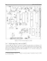
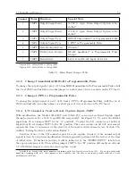
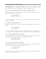
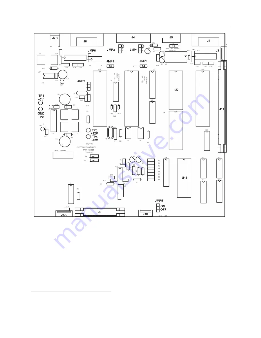
Figure 5.1: Main board and Jumper Locations
5.3.1
Output Signal Type, JMP3 and JMP4
Jumpers JMP3 and JMP4 may be installed to change the output signal type available at I/O
connector J4.
Before installing either of these jumpers, the drill-out via under the jumper location
must be broken, using a small drill in a pin-vise or a sharp blade (such as an X-Acto knife). This
disconnects the original signal from the buffer input.
Note:
Vias are marked by small targets at
the Jumper, shown on Figure 5.1.
1
Note: do not attempt to change these settings on boards whose serial number begins with the digits 9636 without
first contacting the factory.
Summary of Contents for 1092A
Page 4: ...iv ...
Page 18: ...xviii LIST OF TABLES ...
Page 129: ...C 10 Option 20A Four Fiber Optic Outputs 111 Figure C 7 Option 20A Jumper Locations ...
Page 131: ...C 11 Option 27 8 Channel High Drive 113 Figure C 8 Option 27 Jumper Locations ...
Page 148: ...130 Options List Figure C 10 Option 29 Connector Signal Locations ...

