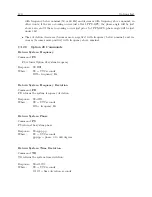
C.12 Option 28: Power System Time, Frequency and Phase Monitor
123
hh:mm:ssU
= Time of Day, UTC
(or)
hh:mm:ssL
= Time of Day, Local
ss
= Status
first character is Reference Status:
0 : Locked;
1 : Unlocked;
second character is clock status per IEEE P1344
+f.fff
signed Frequency Error in Hz.
+t.tttt
signed Time Deviation in seconds.
ppp.pp
Phase Angle, 0 to 360 degrees.
vvv.vv
Line voltage, rms Volts.
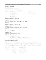
Start Broadcast Mode–True Time
Command:
BT, OT
BT configures the
Standard RS-232
broadcast mode to send Time, Time Quality and Frequency,
once per second, in True Time format. OT configures the
Option RS-232
broadcast mode to send
Time, Time Quality and Frequency, once per second, in True Time format.
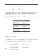
Response:
broadcast mode, UTC:
<
SOH
>
DDD:HH:MM:SSQTsDS.thmFsU.thm
C
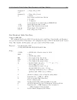
Where:
<
SOH
>
= ASCII start of header character (01h)
DDD
= Day
:
= ASCII colon (3Ah)
HH
= Two digits of the hour of day
MM
= Two digits of the minute of day
SS
= Two digits of the second of day
Q
= Quality Sentry character ( , “.”, “*”, “#”, “?”)
space (20h) error
5
1
µ
s
.
period (2Eh) 1
5
error
<
10
µ
s
*
asterisk (2Ah) 10
5
error
<
100
µ
s
#
pound sign (23h) 100
5
error
<
1000
µ
s
?
question mark (3Fh) error
=
1000
µ
s
T
ASCII T, indicates start of Time Deviation Field
s
Sign cha (2Bh) or - (2Dh)
D
Tens of seconds (Time Deviation
.
Period, decimal point
thm
Tenths, hundredths and thousandths of seconds
F
ASCII F, indicates the start of Frequency Deviation Field
s
Sign cha (2Bh) frequency above nominal or
- (2Dh) frequency below nominal
U
Units of Hertz (Frequency Deviation)
Summary of Contents for 1092A
Page 4: ...iv ...
Page 18: ...xviii LIST OF TABLES ...
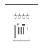
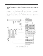
Page 129: ...C 10 Option 20A Four Fiber Optic Outputs 111 Figure C 7 Option 20A Jumper Locations ...
Page 131: ...C 11 Option 27 8 Channel High Drive 113 Figure C 8 Option 27 Jumper Locations ...
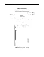
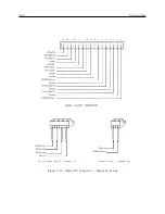
Page 148: ...130 Options List Figure C 10 Option 29 Connector Signal Locations ...

