A.3 I/O Configuration
89
A.2.5
Acquisition
•
150 seconds typical, cold start
•
15 minutes, 90% confidence, cold start
•
40 seconds, with almanac less than one month old
•
15 seconds, with ephemeris less than 4 hours old
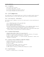
A.3
I/O Configuration
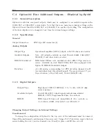
Any output signal, or the designated input, may be selected on specified connector by means of
internal push-on jumpers or special wiring. Each output connector is independently buffered.
A.3.1
I/O Connectors – Main Board
I/O connectors may be configured to any one of the output signals or a specific input function as
listed below:
•
One as IRIG-B unmodulated or Programmable Pulse
•
One as 1 PPS or Programmable Pulse
•
One as IRIG-B, Modulated with Option 92
•
One as Event Input with special wiring and JMP7 set. Can use IRIG-B modulated connector
if unused, or Option 95 with Model 1093A/B/C if Option board slot not used.
•
RS-232 port(s) (standard or second), Auxiliary output at pin 4, Programmable Pulse output
or Event A input. Secondary RS-232 port available with Option 19.
A.3.2
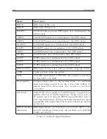
Standard Output Signals
•
IRIG-B: 1 kHz modulated (main board requires Option 92).
•
IRIG-B: 5 V CMOS level-shift (unmodulated), 10-Ohm source impedance;
±
75-mA drive.
•
1 PPS: 5 V CMOS, 10-Ohm source impedance;
±
75-mA drive.
•
IRIG-B, Modified Manchester:
5 V CMOS level-shift (unmodulated), 10-Ohm source
impedance;
±
75-mA drive
A.3.3
Option 03, Four Additional Configurable Outputs
•
IRIG-B: 1 kHz modulated, 10 Vpp (Option 9.
•
IRIG-B: 5 V CMOS level-shift (unmodulated).
•
1 PPS: 5 V CMOS.
•
Out of Lock: 5 V CMOS (HI = Locked, LO = Unlocked).
•
Programmable Pulse, user-selectable: 5 V CMOS.
•
CMOS outputs are buffer type (74HC126) with 10-Ohm source resistors.
A.3.4
Input Functions
•
Event A or 1 PPS Deviation: 5 V TTL/CMOS.
Summary of Contents for 1092A
Page 4: ...iv ...
Page 18: ...xviii LIST OF TABLES ...
Page 129: ...C 10 Option 20A Four Fiber Optic Outputs 111 Figure C 7 Option 20A Jumper Locations ...
Page 131: ...C 11 Option 27 8 Channel High Drive 113 Figure C 8 Option 27 Jumper Locations ...
Page 148: ...130 Options List Figure C 10 Option 29 Connector Signal Locations ...

