90
Technical Specifications and Operating Parameters
A.3.5
Event Input, Option 98 – Main Board
•
This input has a 100-ns timing resolution, and may be configured to record up to 400 sequen-
tial events, provided that the events are separated by at least 11 ms. The event log may be
read later from the front panel or RS-232 interface. A command is also provided to clear the
event log. Event data is stored in battery-backed RAM.
•
The Event A input may also be configured to accept an external 1-PPS signal, and measure
the deviation from a 1-PPS GPS signal with 100-ns resolution.
A.3.6
Synchronization
•
For a received data message, the leading edge of the start bit may be selected to trigger the
Event-A input, providing synchronization with 100-ns resolution.
A.4
System Interface
A.4.1
RS-232C Port
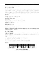
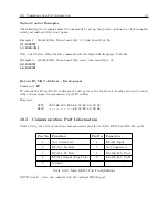
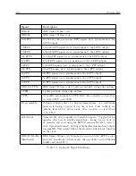
For a list of serial port pins and assigned functions, see Table 10.10.
•
Connector: 9-pin D-type subminiature:
•
RS-422/485 (Option 94): Transmit only.
•
Communication Parameters – Selectable 1,200-19,200 baud; 7 or 8 data bits, 1 or 2 stop bits,
odd/even/no parity.
•
Supports all keyboard functions.
A.4.2
Broadcast Data Formats
For detailed information on all broadcast formats, please see Section 10.2.3.
A.5
Antenna System
The included antenna is directly mounted on a 26-mm pole (1.05-in. OD or 3/4-in. ID pipe), with
either a standard 1-in. – 14 (approximately M25.4 x 1.81) marine-mount thread or a 3/4-in. NPT
pipe thread. Other mounting configurations are available (contact Arbiter Systems).
•
GPS Antenna Assembly, 3/4” Pipe Thread Mount, 35 dB gain; Operates on 5 VDC.
•
Optional Antenna Mounting Bracket available to mount on 60-mm (2-in. nominal) pipe (P/N
AS0044600, see section 4.1.2).
A.5.1
Antenna Cable
•
15-meter (50-foot) cable included with antenna.
•
Other cable styles and lengths available see Table 4.2 under Available Antenna Cables and
Accessories for Longer Runs.
Summary of Contents for 1092A
Page 4: ...iv ...
Page 18: ...xviii LIST OF TABLES ...
Page 129: ...C 10 Option 20A Four Fiber Optic Outputs 111 Figure C 7 Option 20A Jumper Locations ...
Page 131: ...C 11 Option 27 8 Channel High Drive 113 Figure C 8 Option 27 Jumper Locations ...
Page 148: ...130 Options List Figure C 10 Option 29 Connector Signal Locations ...

