


78
Serial Communication and Command Set
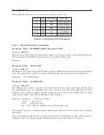
Response:
I=nn:nn X=nn:nn
C
Format:
I = internal clock conditions
X = external clock conditions
nn:nn = hexadecimal representations of the status byte.
The two digits preceding the colon describe present condition of the instrument.
The two digits after the colon indicate the parameters that have changed.
Time Quality
Command:
TQ
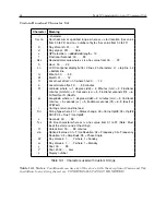
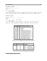
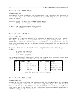
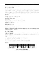
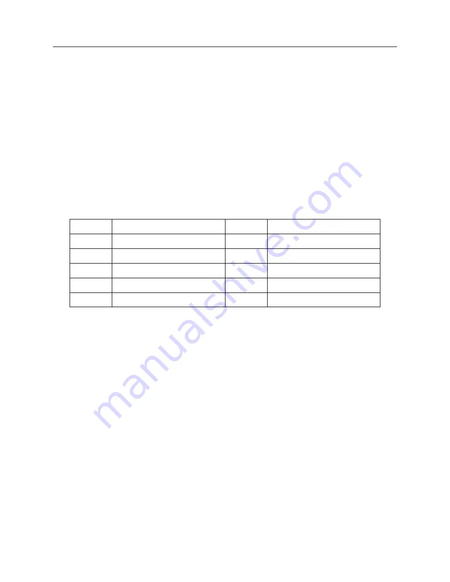
TQ returns a single ASCII character (0, 4–9, A, B, F) indicating estimated worst-case time quality,
which follows the IEEE Standard, P1344. Table 10.7 gives the returned value and error category.
Response: h
C
Value, h
Time Error
Value, h
Time Error
0
Locked, max. Accuracy
8
Unlocked, accuracy
<
10 ms
4
Unlocked,
<
1 us
9
Unlocked,
<
100 ms
5
Unlocked,
<
10 us
A
Unlocked,
<
1 s
6
Unlocked,
<
100 us
B
Unlocked,
<
10 s
7
Unlocked,
<
1 ms
F
Clock failure
Table 10.7: Unlocked Time Quality
10.2.6
Local / Daylight Saving Time Setup Commands
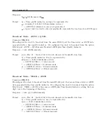
Return Daylight Saving/Summer Time Settings
Command:
0DT
0DT returns the current Daylight Saving / Summer Time settings to the connected RS-232 port
(Modes: OFF, ON, or AUTO).
Response:
Mode
:AUTO
C
START :02:00 Second SUN of MAR
C
STOP :02:00 First SUN of NOV
C
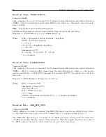
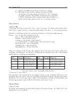
Set Daylight Saving/Summer Time Mode
Command:
1,mDT
1,mDT activates the Daylight Saving mode, where m = 0, 1, 2, with 0 = OFF, 1 = ON, and 2 =
AUTO. When OFF this time adjust feature does not add the specified offset to local time display
and output. With m = 1 (ON), the Daylight Saving / Summertime feature is always on. With m
= 2, the Daylight Saving / Summertime feature will automatically change at the specified dates
Summary of Contents for 1092A
Page 4: ...iv ...
Page 18: ...xviii LIST OF TABLES ...
Page 129: ...C 10 Option 20A Four Fiber Optic Outputs 111 Figure C 7 Option 20A Jumper Locations ...
Page 131: ...C 11 Option 27 8 Channel High Drive 113 Figure C 8 Option 27 Jumper Locations ...
Page 148: ...130 Options List Figure C 10 Option 29 Connector Signal Locations ...