Apcon ACI-3030-T05-1 User Manual Download Page 16

APCON, Inc.

16

A54-3002-027 • Rev B 

Chapter 2 Introduction

Bypass Switch TAP/Aggregator User Manual

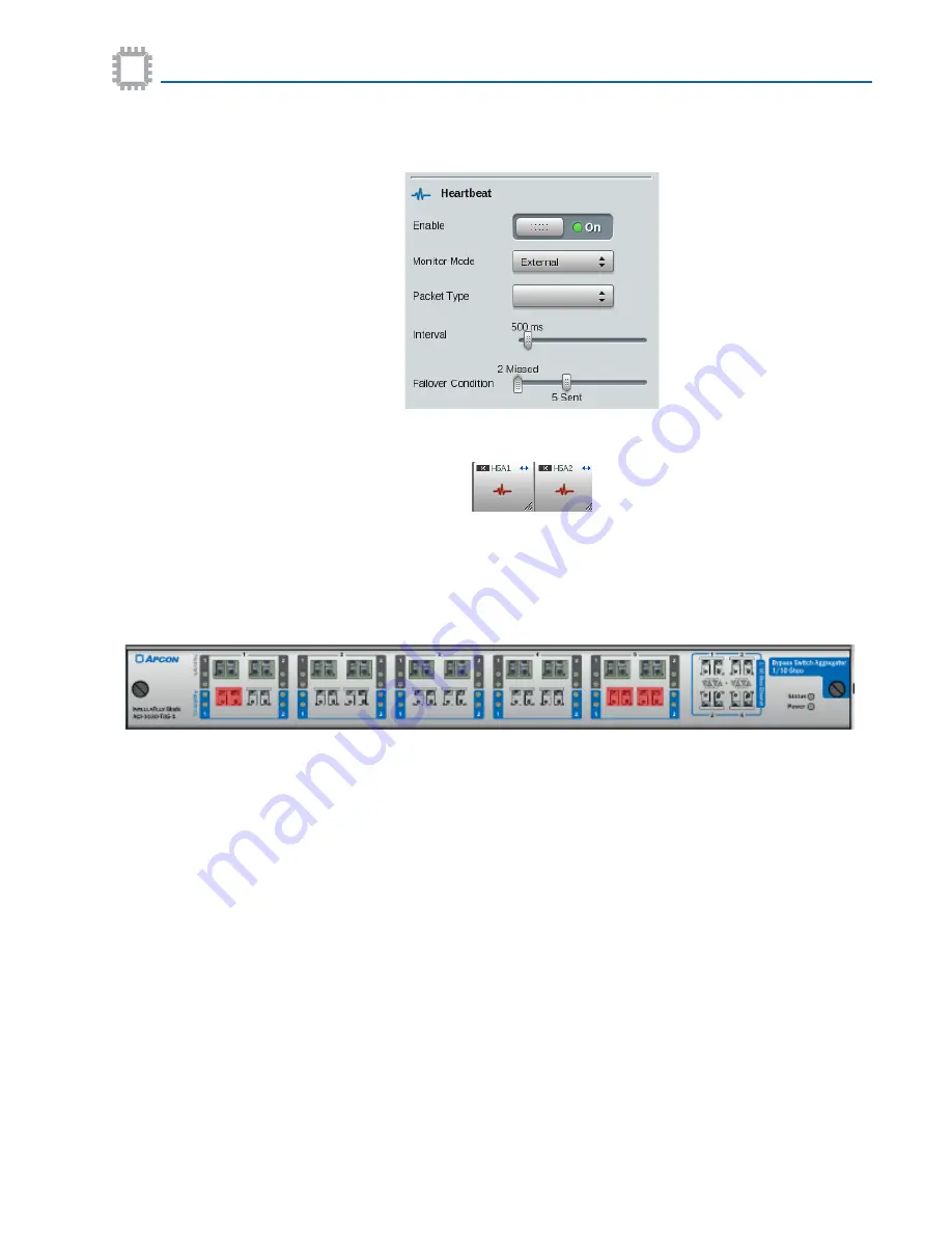
3. The Heartbeat Enable switch remains 

On

 and the blade continues to attempt to send 

heartbeat packets to the appliance.

4. The heartbeat icons on the Appliance ports display red, denoting that the blade is not 

receiving heartbeat packets from the appliance.

If the blade is receiving the required heartbeat packets, the heartbeat icon displays blue. 
However, the blade remains in bypass mode until manually set to Monitor.

5. The W

EB

XR System screen displays a red overlay over only the affected ports on the 

Bypass TAP.

6. The List Alarms tab lists:

• Port failback to Bypass mode
• Port heartbeat lost

7. These alerts are sent to the T

ITAN

XR server and the APCON M

OBILE

A

PP

.

Failback method

The Bypass TAP supports both manual and automatic Failback Method.
When set to Manual the user must:
• set the Port Mode for the corresponding Network ports to


Monitor (Normal)

and

• set the Monitor Enable switch is set to 

On

 (assuming the user did not set it to 

Off

).

When set to Automatic the user must, when configuring the Failback Method:
• set the Port Mode for the corresponding Network ports to


Monitor (Normal)

and

• specify the Failback Window period.

Summary of Contents for ACI-3030-T05-1

Page 1: ...SWITCH TAP AGGREGATOR USER MANUAL An all in one network monitoring solution Fail safe passive TAP in Bypass mode 5 Optical Bypass 1 10G switches Up to 7 in line appliance support Heartbeat monitoring...

Page 2: ...ed in the license or nondisclosure agreement APCON Inc reserves the right to revise this publication from time to time without obligation of APCON to notify any person or organization of such revision...

Page 3: ...Failback method 16 Alarms 17 Chapter 3 Specifications Specifications 19 Physical interface 19 Electrical specifications 20 Front panel connectors 20 LED status indicators 20 LEDs for the blade 20 Port...

Page 4: ...runk port 39 Port profiles 40 Port rates 42 Set bandwidth threshold per port 43 Paired ports 43 Network port settings Network ports 45 Heartbeat Appliance ports 46 Port locking 49 Chapter 5 Aggregatio...

Page 5: ...es book conventions related software products and how to contact APCON Chapter 2 Introduction Provides information on features and functionality of the Bypass Switch Chapter 3 Specifications Provides...

Page 6: ...mat before picking up an ESD sensitive electronic component Convention Description Movement through menu options For example a sequence to view the Ports screen is displayed as Global View Ports MonoT...

Page 7: ...Pv3 is included with the software For more information see the APCON Support Site https support apcon com TITANXR purchased separately is a web accessible centralized point of control to monitor switc...

Page 8: ...t directly from APCON contact your sales representative APCON Inc technical support is available by phone as follows By e mail Sales representative sales apcon com APCON technical support support apco...

Page 9: ...ports Load balancing supporting redundancy Heartbeat monitoring of appliance Up to 14 monitoring tool ports Monitor aggregate and filter traffic Central management using TITANXR or the APCON MOBILE A...

Page 10: ...The Bypass TAP provides advanced network monitoring to select and groom traffic of interest to external monitoring tools using any of the available 14 ports of copper or optical 1G 10G Ethernet System...

Page 11: ...failure degrade in performance require security updates or are off line for maintenance The Bypass TAP provides heartbeat functionality to automatically detect a faulty link and pass data through the...

Page 12: ...mode where network traffic passes through the blade from both directions to a network tool Bypass mode If the connection between the Bypass TAP and the network tool fails the blade shifts into Bypass...

Page 13: ...occurred and switches from Monitor to Bypass mode In the above diagram network traffic entering the blade from Network ports A1N1 and A1N2 have heartbeat packets inserted into the data streams If the...

Page 14: ...ss mode In either event WEBXR and or TITANXR sends an alert notifying of the loss If the APCON MOBILE APP is configured the alert is also sent to those users who have been configured to receive alerts...

Page 15: ...ss mode corrects itself within the specified Failback Window the port automatically switches back to Monitor Normal mode Failback occurs within 10 seconds of detecting the absence of the required hear...

Page 16: ...itor 5 The WEBXR System screen displays a red overlay over only the affected ports on the Bypass TAP 6 The List Alarms tab lists Port failback to Bypass mode Port heartbeat lost 7 These alerts are sen...

Page 17: ...the ports go into Bypass mode for a reason other than the being set manually to Bypass mode then the paired ports are placed in alarm mode If a pair of Network ports are set to Monitor Normal mode and...

Page 18: ...APCON Inc 18 A54 3002 027 Rev B Chapter 2 Introduction Bypass Switch TAP Aggregator User Manual...

Page 19: ...d Operating Environment temperature 32 F to 113 F 0 C to 45 C Storage temperature 40 F to 158 F 400 C to 70 C Operating relative humidity 10 to 80 non condensing Storage relative humidity 0 to 95 non...

Page 20: ...R GUI plus CLI 2 LAN management ports back of chassis 1 CLI management port back of chassis HTTPS and SSH for secure access TACACS RADIUS and LDAP authentication INTELLAFLEX XR Features user ports Agg...

Page 21: ...e embedded in the switch supports a browser based graphical user interface plus full command line and SNMP interfaces Status LED Solid Illuminates during power up initialization Slow blinking Blinks d...

Page 22: ...Current Revision ACI 3011 E04 10 0 INTELLAFLEX with 100G ports Blade with 4 each 100G Ethernet ports Must be used with an INTELLAFLEX blade in the same chassis supports 1G 10G 40G aggregations to fro...

Page 23: ...Multi Mode SFP ACI 0201 200 R Single Mode SFP ACI 3033 S14 1 INTELLASTORE II Blade with 12 each 1G 10G 2 each 40G ports Features both standard INTELLAFLEX and Multi Function features packet capture p...

Page 24: ...be ordered from APCON Transceiver Transmit power nominal Receiver sensitivity ACI 0201 199 R Dual Rate 1 10 Gbps Multi Mode SFP 5 6 dBm to 3 0 dBm 5 4 dBm 10 5 Gbps ACI 0201 200 R Dual Rate 1 10 Gbps...

Page 25: ...ct the unopened carton for signs of damage or water stains If carton is damaged contact the freight carrier for an inspection of the carton and contents 2 Unpack the carton and place components on a t...

Page 26: ...d in the same slot the chassis retains configuration information rates patches filters and so on To install a new blade or to replace a blade in the chassis 1 Hold the blade by its outer edges in fron...

Page 27: ...ly connected to network tools Heartbeat packets can be inserted into the data stream prior to the data leaving the Appliance ports When the network traffic returns from the Appliance ports the heartbe...

Page 28: ...Monitor Mode When heartbeat packets are inserted into the network traffic stream and being detected on the return cable the heartbeat icon is displayed blue Appliance Ports Bypass Mode If an Applianc...

Page 29: ...e port and if so the status of the SFP Signal strength Displays the signal strength within the port icon Check ports to see if there are weak or faulty fiber optic cables Port Statistics View a limite...

Page 30: ...hically displays the transceiver s receive RX signal strength for each port on the selected blade Signals are shown in decibels dBm and are rounded to the nearest 0 05mW The RX signal strength for tha...

Page 31: ...about setting port profiles to reduce oversubscription Set warnings and alarms for ports WEBXR displays a variety of warnings and alarms to alert about problems with particular ports The warnings and...

Page 32: ...ings and alarms refer to the WEBXR User Manual View bandwidth thresholds for ports Bandwidth warnings and alarms are displayed on the following screens On the Ports page On the View page This section...

Page 33: ...bout the vendor transmission media and protocols For information about transceivers supported in XR chassis see SFP ports and transceivers supported on page 23 Vendor details Click the arrow for Vendo...

Page 34: ...lects statistics for ports that are located on an INTELLAFLEX blade or for ports that are part of an aggregated connection that includes an INTELLAFLEX port Port Statistics can be viewed in the follow...

Page 35: ...on a Network port and select Port Properties from the pop up menu the following window is displayed Each of the settings are described in the sections that follow Right click on an Appliance port and...

Page 36: ...tting on or off To set view options for Port Properties 1 Right click any port on any blade and from the pop up menu select Port Properties 2 At the top of the Port Properties window click the drop do...

Page 37: ...allowed ports user raw names 4 Optional Select another individual port and enter a Port Name 5 When finished click Save 6 Go to the WEBXR Ports page to view Port Names To modify or clear Port Names fo...

Page 38: ...Properties dialog Paired port rules The following rules apply to paired ports Each pair of adjacent ports in a segment are by default paired When paired Appliance ports are connected to a network tool...

Page 39: ...ect Ports 3 On the Ports page select the port that is to function as a trunk connection between the two chassis and click the soft arrow 4 From the pop up menu select Port Properties On the Port Prope...

Page 40: ...agement can reduce oversubscription of ingress traffic to handle bursty traffic patterns Buffer management can be allocated either per port or for a group of ports This feature can be used with Enhanc...

Page 41: ...e drop down menu 5 Click Save Profile Level Maximum number of transmitting descriptors Default 25 Enhanced Shares buffers between ports in a Port Group allows the maximum number of transmitting descri...

Page 42: ...arrow for the Global View icon From the pop up menu select Ports 2 On the Ports page select a port and click the soft arrow 3 From the pop up menu select Port Properties 4 In the lower left side of th...

Page 43: ...erify that the Enable Upper Limits checkbox is selected this is the default setting to enable the upper limit warning and alarm 6 Enter the limits to use for warnings and alarms Limits are a percentag...

Page 44: ...igure the unit Bypass Switch TAP Aggregator User Manual 3 Go to the Paired Ports area 4 Click the slider to pair the selected port with the adjacent port The indicator turns green the selected port an...

Page 45: ...w 3 From the pop up menu select Port Properties 4 Go to the section for Port Mode 5 By default Network ports are set to Bypass When connected in an aggregation the port switches to Monitor Normal 6 To...

Page 46: ...is set to Internal The Failover Condition sliders specify the number of heartbeats to be Sent at the specified Interval If the number of heartbeats specified by Missed occurs within the specified Inte...

Page 47: ...ppliance ports and an attached appliance Packet Type Pull down menu Selectable Blank Lists current filters to filter heartbeat packets from the connected appliance A filter should be created and appli...

Page 48: ...lt is 5 The range is 1 to 10 iv Click the Enable slider to activate the heartbeat v Repeat this procedure for any additional Appliance ports that are to have the heartbeat enabled vi Go to Step 6 If M...

Page 49: ...User Manual for details When a port is locked other users cannot disconnect the port or a connection using that port use the port as part of a new connection change the Port Name or port rate apply o...

Page 50: ...th is restricted to a total of 99 characters 8 Click Save The selected ports are locked for the duration specified 9 A Lock icon displays on the blade for a port or disk drive In addition hovering the...

Page 51: ...er 4 Install and configure the unit 3 From the pop up menu select Port Properties 4 Go to the section for Port Locking 5 Click the button for Lock Port to turn OFF Port Locking 6 Click Save This remov...

Page 52: ...APCON Inc 52 A54 3002 027 Rev B Chapter 4 Install and configure the unit Bypass Switch TAP Aggregator User Manual...

Page 53: ...t within a segment and select Duplex Pair 2 Click Set Chapter 5 Aggregation examples Chapter 5 Creating a bypass aggregation within a segment 53 Creating a bypass aggregation between two different seg...

Page 54: ...the segment with the color yellow 3 Click an Appliance ports in the same segment Both of the Appliance ports are highlighted with the color yellow 4 Click Confirm The Confirm Connection pop up window...

Page 55: ...trates how to create an aggregation from one segment to another segment on the same blade 1 On the WEBXR Global View Port screen click a Network port within a segment and select Duplex Pair This actio...

Page 56: ...h the color yellow 4 Click Confirm The Confirm Connection pop up window displays The Network port H5N1 has a duplex aggregation to the Appliance port H4A1 The Network port H5N2 has a duplex aggregatio...

Page 57: ...up 1 On the WEBXR Global View Port screen click a Network port within a segment and select Duplex Pair This action highlights both of the Network ports in the segment with the color yellow 2 Click Set...

Page 58: ...1 and B3A1 This action highlights Appliance ports A2A1 A2A2 A3A1 and A3A2 ports in amber 7 Click OK 8 The Create Load Balance Group pop up window closes 9 On the Ports screen the new LBG icon is displ...

Page 59: ...s B2A2 and B3A2 11 If desired enter the optional Patch Name Job Ticket and or Message fields 12 Click Save The Confirm Connection window closes and the LBG aggregation is configured 13 A bypass aggreg...

Page 60: ...de receives the heartbeat packets from the network tool consistently for one minute the blade automatically shifts back into Monitor mode The one minute value is based on the user setting that allows...

Page 61: ...liance ports As the heartbeat packets enter the blade through either the A1 or A2 ports the blade would identify them as heartbeat packets and filter them out of the data stream If the user specified...

Page 62: ...the Appliance ports If the user specified number of heartbeat packets do not return the corresponding Network ports shift to Bypass mode External The blade monitors the heartbeat packets coming from...

Page 63: ...window the embedded x86 processor it must first be shut down before performance any maintenance or upgrades otherwise data may be lost Chapter 6 Maintenance Chapter 6 Installing Removing a blade 64 Vi...

Page 64: ...n information rates patches filters and so on To install a new blade or to replace a blade in the chassis 1 Hold the blade by its outer edges in front of the target slot 2 Align the back edges of the...

Page 65: ...the WEBXR Global View Ports page 2 Click the soft arrow in the lower right corner of the blade 3 From the pop up menu select Turn blade power off To remove a blade 1 After the blade powers down take...

Page 66: ...al number and information about current and suggested firmware An option to view and set individual transceiver warnings and alarms is provided In addition a firmware upgrade option is available To vi...

Page 67: ...he colors see below Type Lists the type of APCON blade Model Lists the model number for the installed blade Serial Number Lists the serial number for the installed blade Current Device Firmware Curren...

Page 68: ...Whenever communications cannot be repeated clean the connectors To extend the life of transceiver modules use care when handling installing and removing fiber optic cables To clean connectors 1 Grasp...

Page 69: ...Wait a few seconds for the surfaces to dry and repeat for the other ferrule 5 Visually inspect the ferrule for dust and lint then clean again if necessary The connectors must be absolutely free of tra...

Page 70: ...APCON Inc 70 A54 3002 027 Rev B Chapter 6 Maintenance Bypass Switch TAP Aggregator User Manual...

Page 71: ...handling 69 cable test 30 Caution label 6 change individual Port Name 37 characters restricted in XML 50 chassis install blade 26 64 replace blades 26 64 check signal strength 30 Class 1 laser produc...

Page 72: ...g 50 M maintenance 63 back up first 63 cable test 30 N names Port Names 37 NETVIS 7 notifications 6 O operating specifications 19 oversubscription Enhanced Port Profile 40 Enhanced Port Profiles 41 En...

Page 73: ...SFPs dual rate transceivers 42 signal receive RX 20 signal strength 30 soft arrow 6 software APCON products 7 specifications electrical 20 operations 19 physical unit 19 static electricity 26 statist...

Page 74: ...PCON Inc 74 A54 3002 027 Rev B Index Bypass Switch TAP Aggregator User Manual V View Options Port Properties 36 W website for APCON 8 WEBXR software 7 weight of blade 19 X XML restricted characters 50...

Reviews: