68
IMGT30017EN
6A.6
SAFE STOP BOARD
Introduction
For the detailed description and operating instructions refer to:
O P E R A T I N G I N S T R U C T I O N S S A F E T Y F U N C T I O N : “STO”SAFE TORQUE OFF FOR GT3000 INVERTER
Number
Rev.
Date
MIM046
14
09/01/08
The "EC Declaration of Conformity" shall apply providing that all the operating conditions described in this document are complied with.
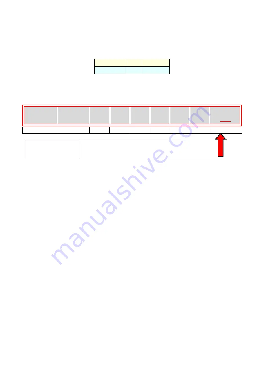
6A.6.1 Identification procedure for the safety function
The components related to the function are installed inside the drive in our works and the presence of the same in the drive is identified by the
suffix “70” of the identification code of the drive.
SVGT
166
F
E
N
F
N
N
70
1,2,3,4
5,6,7
8
9
10
11
12
13
14,15
Suffix
(Special options)
Absent (standard drive)
21
= Bus DC supply with internal precharge
70
=
SAFE TORQUE OFF Function
6A.6.2 Application field
The STO safety function has been conceived to ensure the "
SAFE TORQUE OFF
" function with inverter-supplied asynchronous motors.
If the STO function is enabled, no rotating field is generated in the motor connected to the inverter.
The safety function is activated by two independent channels, which feature a different technology.
The first channel de-energizes – by a safety relay – the electronic devices (drivers, photocouplers, optical fibres, buffers), which send control
pulses to the power section; in these conditions, even if the regulation electronics generate control pulses, the power section would no longer
move the connected motor.
The other channel prevents both pulse generation by the microprocessor and pulse propagation to the control section.
With reference to the block diagram below, safety relay RL1 has two contacts (open/closed), which are mechanically connected in such a way
that they cannot be opened or closed at the same time even in case of failure (e.g. open/closed glued contacts). The NO (Normally Open)
contact powers the drive, while the NC (Normally Closed) contact ensures signalling for monitoring the state of the safety function by an
external system.
The activation state of the second channel is signalled by a digital output of the micro, which controls the rl2 relay.
6A.6.2.1
Safety functions and relevant levels
The "STO" safety function has been designed to prevent the unexpected start-up of the motor. A motor, when off, can be put in the state of
"
SAFE TORQUE OFF
" by the “STO” safety function. In this condition, also in the absence of a galvanic separation between motor and
inverter or network and inverter, some mechanical works can be performed on the actuator.
Warning!!
In the "SAFE TORQUE OFF" state the motor’s terminals are not isolated from the mains and therefore they could be live!
The “STO” function has been designed to prevent the unexpected start-up of the motor, and not to stop it: if activated while the
motor is revolving, it will be stopped in an uncontrolled way. If an uncontrolled stop is not desired, complete a stop sequence before
enabling the “STO” function.
A motor in the "SAFE TORQUE OFF" state may not generate any torque. In order to stop a revolving motor with a load torque
applied to the axis, install a mechanical brake.
There is a residual risk: in the event of a simultaneous failure of two IGBTs, the motor may have – up until the activation of the
drive/fuse protection devices – a small rotation angle (360°/2P, with P = number of couples of poles in brushless motors, a tooth
pitch in induction motors) even if the "SAFE TORQUE OFF" function is enabled.
The STO function:
complies with EN 60204-1:2006, paragraph 5.4 "Devices for switching off for prevention of unexpected start-up", but does not
comply with paragraph 5.3 "Devices for isolation and switching";
fits for the stop function according to categories 0 - 1 in accordance with EN 60204-1, paragraph 9.2.2.;
can meet the safety requirements of the harmonized standard UNI EN 954-1:1998 categories 3 or 2, as regards the restart block
according to the configuration mentioned in paragraph 2.2.
Summary of Contents for GT3000
Page 1: ...GT3000 Hardware Software Manual www answerdrives com ...
Page 2: ......
Page 4: ......
Page 8: ...Table Of Contents GT3000 iv IMGT30017EN ...
Page 12: ...General Safety Precautions viii IMGT30017EN ...
Page 25: ...GT3000 Technical Data IMGT30017EN 13 Frames IV V VIN SVGT045 166 IP20 ...
Page 26: ...Technical Data GT3000 14 IMGT30017EN Frames IV V VIN SVGT045 166 IP54 ...
Page 28: ...Technical Data GT3000 16 IMGT30017EN Frames VII VIII IP00 SVGT200 521K SVGT200 470F ...
Page 29: ...GT3000 Technical Data IMGT30017EN 17 F series Frames 2xVII 2xVIII Parallel IP00 SVGT520 940M ...
Page 30: ...Technical Data GT3000 18 IMGT30017EN K series Frames 2xVII 2xVIII Parallel IP00 SVGT580 960K ...
Page 36: ...Installation GT3000 24 IMGT30017EN 3A 2 1 4 Frames VII VIII Installatiion ...
Page 58: ...GT3000 Installation 46 IMGT30004EN ...
Page 107: ...GT3000 Terminal Boards and Power Schematics IMGT30017EN 95 ...
Page 110: ...Terminal Boards and Power Schematics GT3000 98 IMGT30017EN ...


