1-4 Chapter Introduction
General GPIB Information
1-2
PN: 10370-10374 Rev. F
MG369xC GPIB PM
1-4
Chapter Introduction
This chapter provides a general description of the GPIB and the bus data transfer and control functions. It also
contains a listing of the MG369xC's GPIB interface function subset capability and response to IEEE-488
interface function messages.
The GPIB information presented in this chapter is general in nature. For complete and specific information,
refer to the following documents: ANSI/IEEE Std 488.1-1987
IEEE Standard Digital Interface for
Programmable Instrumentation
and ANSI/IEEE Std 488.2-1987
IEEE Standard Codes, Formats, Protocols
and Common Commands
. These documents precisely define the total specification of the mechanical and
electrical interface, and of the data transfer and control protocols.
1-5
IEEE-488 Interface Bus Description
The IEEE-488 General Purpose Interface Bus (GPIB) is an instrumentation interface for integrating
instruments, computers, printers, plotters, and other measurement devices into systems. The GPIB uses 16
signal lines to effect transfer of information between all devices connected on the bus.
The following requirements and restrictions apply to the GPIB.
•
No more than 15 devices can be interconnected by one contiguous bus; however, an instrumentation
system may contain more than one interface bus.
•
The maximum total cumulative cable length for one interface bus may not exceed twice the number of
devices connected (in meters), or 20 meters—whichever is less.
•
A maximum data rate of 1 Mb/s across the interface on any signal line.
•
Each device on the interface bus must have a unique address, ranging from 00 to 30.
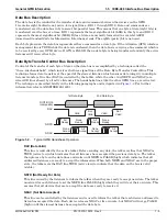
The devices on the GPIB are connected in parallel, as shown in
. The interface consists of
16 signal lines and 8 ground lines in a shielded cable. Eight of the signal lines are the data lines, DIO 1
through DIO 8. These data lines carry messages (data and commands), one byte at a time, among the GPIB
devices. Three of the remaining lines are the handshake lines that control the transfer of message bytes
between devices. The five remaining signal lines are referred to as interface management lines.
The following paragraphs provide an overview of the GPIB including a description of the functional elements,
bus structure, bus data transfer process, interface management bus, device interface function requirements,
and message types.
Summary of Contents for MG369 C Series
Page 2: ......
Page 6: ...Contents 4 PN 10370 10374 Rev F MG369xC GPIB PM ...
Page 262: ...A 34 PN 10370 10374 Rev F MG369xC GPIB PM ...
Page 264: ...Index 2 PN 10370 10374 Rev F MG369xC GPIB PM ...
Page 265: ......


