


Open the parameter you wish to change, then edit
the current value using the cursor control key or the
rotary data knob or enter a new value using the key
pad and appropriate termination key. When you
have finished setting the open parameter, close it by
pressing its menu soft-key or make another menu
selection.
Press
More
to go to the Additional Step Sweep
Ramp menu.
Press
Previous Menu
to return to the Step Sweep
Menu display.
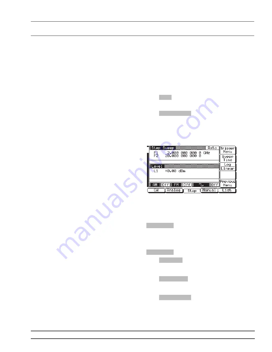
Additional Step Sweep Ramp Menu
When you press More, the Additional Step Sweep
Ramp Menu (below) is displayed.
This menu lets you set the sweep time, select loga-
rithmic or linear step sweep, and go to the trigger
menu.
To open the sweep time parameter for editing, press
Sweep Time
. Edit the current sweep time using the
cursor control key or the rotary data knob or enter a
new sweep time using the keypad and appropriate
terminator key. To close the open sweep time pa-
rameter once you have set the desired time, press
Sweep Time
or make another menu selection.
Press
Log/Linear
to select logarithmic or linear step
sweep operation. The soft-key label is highlighted
(in reverse video) to reflect your selection.
Press
Trigger Menu
to go to the Step Sweep Trigger
menu. The trigger menu lets you select a sweep trig-
ger (previously described on page 3-28).
Press
Previous Menu
to return to the Step Sweep
Ramp Menu display.
681XXC OM
3-31
LOCAL (FRONT
SWEEP FREQUENCY
PANEL) OPERATION
OPERATION
Summary of Contents for 680XXC
Page 3: ......
Page 11: ...Table of Contents Continued...
Page 13: ...Figure 1 1 Series 681XXC Synthesized Signal Generator...
Page 21: ......
Page 37: ......
Page 128: ......
Page 130: ......
Page 131: ...LOCAL OPERATION SAMPLE MENU MAPS MENU MAP Figure 4 1 Sample Menu Map Annotated 681XXC OM 4 5...
Page 146: ......
Page 191: ......
Page 206: ......