


2-5
RACK MOUNTING KIT
INSTALLATION
The rack mounting kit (Option 1) contains a set of track slides (90
°
tilt
capability), mounting ears, and front panel handles for mounting the
signal generator in a standard equipment rack. The following proce-
dure provides instructions for installing the rack mounting hardware
on to the instrument. Refer to Figures 2-2 and 2-3 during this proce-
dure.
Preliminary
Disconnect the power cord and any other cables
from the instrument.
Procedure
Install the rack mounting hardware as follows:
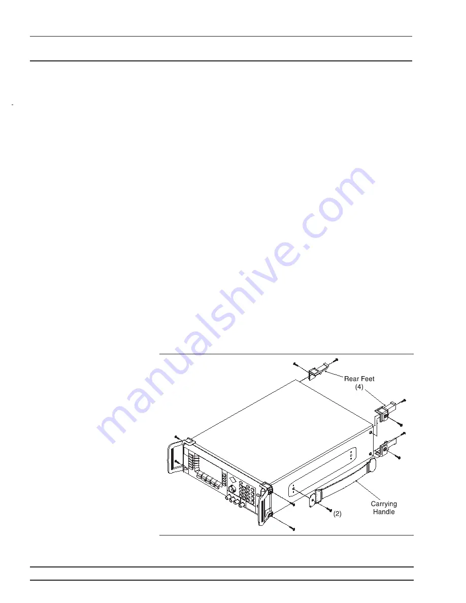
Step 1
Using a Phillips screwdriver, remove the
screws and the front handle assemblies
from the instrument. (For instruments
not having front handles, remove the
screws and the front top and bottom feet
from the instrument.) Retain the screws.
Step 2
Remove the four feet from the rear of the
instrument. Retain the screws.
Step 3
Remove the screws and the carrying han-
dle from the side handle cover. (The two
screws fastening the carrying handle
through the side handle cover to the chas-
sis are accessable by lifting up the rubber
covering at each end of the handle.)
2-10
681XXC OM
RACK MOUNTING KIT
INSTALLATION
INSTALLATION
Figure 2-2.
Front Handle, Feet, and Carrying Handle Removal
Summary of Contents for 680XXC
Page 3: ......
Page 11: ...Table of Contents Continued...
Page 13: ...Figure 1 1 Series 681XXC Synthesized Signal Generator...
Page 21: ......
Page 37: ......
Page 128: ......
Page 130: ......
Page 131: ...LOCAL OPERATION SAMPLE MENU MAPS MENU MAP Figure 4 1 Sample Menu Map Annotated 681XXC OM 4 5...
Page 146: ......
Page 191: ......
Page 206: ......