AngioDynamics NanoKnife User Manual Download Page 35

35 

160-104694 Rev 01 
Version 2.2.0 


Procedure Date – The 

Procedure Date and Time

 are automatically set by the 

system. 


Physician Name – Optional 


Case Notes – Optional 

The 

Clinical Data

 section allows the User to type clinical information and tissue 

specifications in the appropriate fields. 


Clinical Indication Notes – Optional 


Lesion Zone (cm) – (Length, Width and Depth) – Optional, can be entered by typing 
or with the Up/Down arrows. 


Margin – Optional, can be entered by typing or with the Up/Down arrows. 


Target Zone (cm) – (Length, Width and Depth) cannot be modified by typing and is 
based on Lesion Zone value plus two times what the value is of the Margin Zone. 

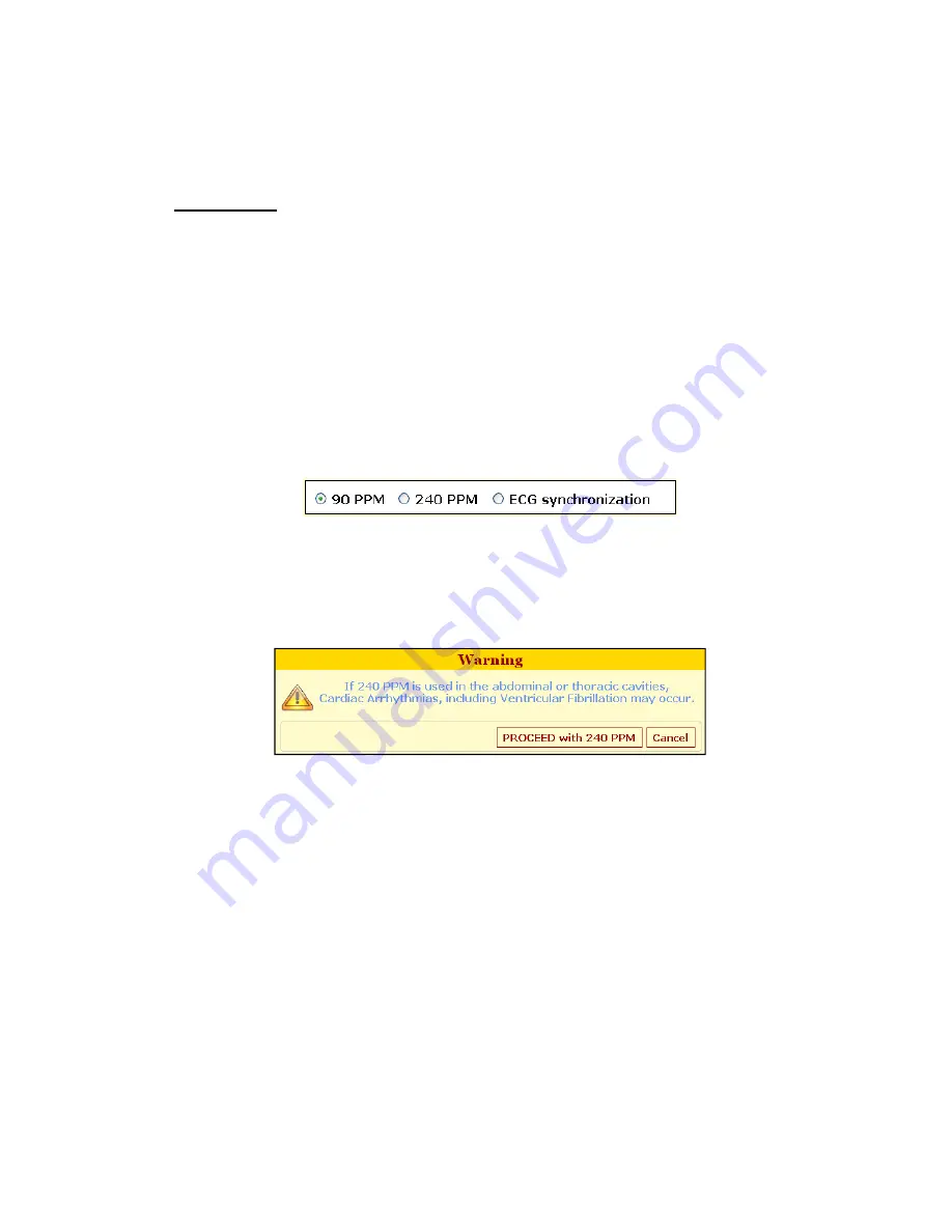
The Pulse Timing Control, Figure 5-2, consists of three radio buttons that allow the User to 
select 90 PPM, 240 PPM, or ECG synchronization (default setting) to set the timing of the 
pulses. 


Figure 5-2: Pulse Timing Control 

NOTE: 90 PPM should be selected for soft tissue procedures below the waist and 240 PPM 
for prostate procedures, otherwise ECG Synchronization (default setting) should be used. A 
pop-up warning window will appear if User setting is 240 PPM, Figure 5-3.  


Figure 5-3: Pop-Up Warning Window 


Summary of Contents for NanoKnife

Page 1: ......

Page 2: ...noKnife is a registered trademark of AngioDynamics with patents pending in the United States and foreign countries This documentation contains proprietary information of AngioDynamics No part of this...

Page 3: ...cution Hazard 13 2 5 Precautions 14 2 5 1 Side Effects 15 SECTION 3 SYSTEM COMPONENTS 17 3 1 Overview 17 3 2 Generator Description 18 3 2 1 Generator Front Right Side Elements 18 3 2 2 Generator Front...

Page 4: ...TION 71 6 1 Overview 71 6 2 External R Wave Detector 71 SECTION 7 PROBES AND ABLATION AREA 77 7 1 Electrode Probes 77 7 2 Ablation Area 77 SECTION 8 TROUBLE SHOOTING 79 8 1 Overview 79 8 2 Documented...

Page 5: ...ng Conditions 88 10 5 Classifications 88 10 6 Use Conditions 89 10 7 Technical Specifications 89 10 8 Radio Frequency Identification 90 SECTION 11 WARRANTY AND ELECTROMAGNETIC COMPATIBILITY 91 11 1 Wa...

Page 6: ...6 160 104694 Rev 01 Version 2 2 0...

Page 7: ...s outside of the sterile field The second component of the NanoKnife System is a Footswitch for the Generator The footswitch connects to the Generator and also operates outside the sterile field The l...

Page 8: ...xcept main voltage Caution Indicates that the User should read the accompanying documentation in order to understand and or correctly use the part marked by the symbol On the LCD display and data plat...

Page 9: ...2 Specific Part Symbols Symbol Meaning Location USB Port Connector for USB storage device e g USB Flash Drive It is not recommended to connect any other kind of device On the side of the console Conso...

Page 10: ...clicked or are graphical User interface elements that provide options Icon Function Description Generator User login icon Radio or Option Button Various procedure screens on the console allow the Use...

Page 11: ...serious adverse events involving the patient User any other person or the environment Precautions are safety instructions that if neglected might lead to undesired events of marginal or negligible sev...

Page 12: ...iating a procedure if the probes are too far apart or too close together 2 3 Contraindications Procedures based on high voltage pulses are not recommended in the following cases Ablation of lesions in...

Page 13: ...lowing a Disconnect any electrode from the Generator that is not applied to the patient b Avoid any clamping of the electrode s cable unless explicitly instructed or authorized by the electrode s manu...

Page 14: ...ontemplated only after ensuring that the procedure benefits outweigh the risks Procedure safety and efficacy may be affected if electrodes other than those supplied by AngioDynamics or by an authorize...

Page 15: ...rrect ventilation of the internal circuits Avoid moving the device when powered ON Avoid jarring the equipment during transport Avoid scratching the LCD display Before carrying out any cleaning of the...

Page 16: ...16 160 104694 Rev 01 Version 2 2 0...

Page 17: ...m Generator utilizes single use disposable electrode probes to transmit energy from the Generator to a target ablation area The Generator Trolley in Figure 3 1 includes the following LCD Display Conso...

Page 18: ...e the names of the Generator elements are listed in Table 3 1 3 2 1 Generator Front Right Side Elements Table 3 1 Generator Front Right Side Elements Figure 3 2 Generator Front Right Side Elements Fig...

Page 19: ...identified by the label STOP When pressed internally disconnects the electrode connectors Allows interruption of procedure without removing electrodes from the patient Accumulated energy in the power...

Page 20: ...synchronization of the ablation Figure 3 4 Generator Power Unit s Back Lower Panel Elements Table 3 3 Generator Power Unit s Back Lower Panel Elements Refer to Figure 3 4 Component Description 1 Powe...

Page 21: ...Generator Back Handle 3 2 5 Equipment and Supplied Components Table 3 4 lists the Generator components and supplied quantities Table 3 4 Equipment and Supplied Components NOTE The Double Foot Pedal i...

Page 22: ...ically optimize the display position clock and phase of the display 2 Exit Back Press to exit the On Screen Display OSD or to return to previous level 3 Minus If OSD is active press to select or adjus...

Page 23: ...Press the button to open the On Screen Display OSD menu 2 Use the buttons marked or to highlight a control then press the button to enter 3 Use the buttons marked or to adjust the control to the desir...

Page 24: ...switched ON 2 Caps Lock Indicator identified by the symbol When lighted indicates that the keyboard s letter keys are in uppercase 3 Hard Disk Function Light indicator identified by the HDD symbol Whe...

Page 25: ...e Single Electrode Activation Probe is required to activate the generator which will allow other standard Single Electrode Probes to function with it Only one Single Electrode Activation Probe is requ...

Page 26: ...26 160 104694 Rev 01 Version 2 2 0...

Page 27: ...d in relationship to its ventilation grids remain at least 5 cm centimeters away Care must be taken to avoid items e g dust covers that can occlude the ventilation grids WARNING The Generator must be...

Page 28: ...e operating system b Allow about 10 seconds for the video signal to appear on the LCD display c Check that the STOP button status Indicator on the Generator s front panel is lit Green If not lit rotat...

Page 29: ...ls an error message will be displayed Figure 4 3 is an example of an error message The User must then click OK which will shut down the generator so that it can be restarted Figure 4 3 Example of Erro...

Page 30: ...30 160 104694 Rev 01 Version 2 2 0...

Page 31: ...probe is required 4 Make probe selection configuration 5 Define ablation area 6 Place probes at targeted ablation site 7 Confirm or specify procedure pulse settings 8 Deliver test pulse button on the...

Page 32: ...efault parameters is displayed in the table Delete Row button on the Probe Placement Process screen allows the User to remove a probe pair pulse sequence from the ablation pulse configuration Edit but...

Page 33: ...creen allows the User to start the delivery of test pulses Abort Delivery button on the Pulse Generation screen allows the User to stop the delivery of pulses at any time New Patient button on the Pul...

Page 34: ...generator to input information From now on Select will refer to a click either via a mouse or the touch pad buttons or by physically touching the screen The Patient Information section allows the Use...

Page 35: ...he Up Down arrows Target Zone cm Length Width and Depth cannot be modified by typing and is based on Lesion Zone value plus two times what the value is of the Margin Zone The Pulse Timing Control Figu...

Page 36: ...ation in the Information screen as described below The Patient Information section Enter Patient ID number which is a required field using any numbering system that the User chooses Name and Age are n...

Page 37: ...the three areas that will need to be completed in the Information screen by selecting the desired configurations Figure 5 7 Figure 5 7 Clinical Data Screen The Lesion Zone cm popups allow the User to...

Page 38: ...When the Lesion zone is configured and saved the system automatically sets the Target zone dimensions based upon the margin Figure 5 10 Figure 5 10 Lesion Zone Configured The Margin zone is the distan...

Page 39: ...tically set Physician name and Case notes are optional areas to complete Figure 5 13 Figure 5 13 Case Information Screen After completing the Information section select the next button Figure 5 14 to...

Page 40: ...acement and estimated ablation size The User is required to specify one of the probe type configurations for ablation according to the extent of the desired ablation zone by selecting on the adjacent...

Page 41: ...r Reference source not found The Probe Type section includes the following eight probe type configurations Bipolar Two probe array Three probe array Four probe array Five probe array Six probe array S...

Page 42: ...42 160 104694 Rev 01 Version 2 2 0 Three Probe Array Four Probe Array Five Probe Array...

Page 43: ...43 160 104694 Rev 01 Version 2 2 0 Six Probe Array Six Probe Array 10 mm Six Probe Array 15 mm...

Page 44: ...User may select the specific probes to be used for the procedure by selecting on the probe number The probe numbers correspond to the ports on the front panel of the Generator see Figure 5 15 Figure 5...

Page 45: ...lid Red Not Connected Grey Figure 5 17 Invalid Not Connected Probes NOTE The User cannot progress to the next screen without at least one valid Activation probe connected to the Generator Once the des...

Page 46: ...here ablation parameters are defined and ablation Pulse Settings are set It consists of the Probe Placement Grid Procedure Spreadsheet Voltage Default Setting Box Probe Dock Undock and Exposure Table...

Page 47: ...0 below that the User can choose based on the size of the ablation and the number of probes required to treat the area in the Probe Placement Process screen Biopolar Probe Two Probe Three Probe Four P...

Page 48: ...ia by clicking o hem he distances he grid and en Dragging 48 m grid that is shown in F ne and plan e Zone Rotat ent Grid and O ere on the gr options to Hid steps and ch w or Hide Rota nd B are fid eas...

Page 49: ...s the pro ressed e The Green p down righ be 1 49 Show or Hid User to switc oint click on the Fiducial etween Prob istance betw d marked wit how the Pro om Probe 1 t 5 24 Referenc er are as foll lesion...

Page 50: ...ed by dragging and dropping each probe Ablation size and shape will be automatically updated to the Procedure Spreadsheet Once selected probes can be moved in 1 mm increments by using the Up Down Left...

Page 51: ...under the placement grid as shown in Figure 5 28 Figure 5 28 Screen Buttons The Zoom In and Zoom Out buttons enlarge or decrease views of grid to display a 7 x 7 view or a 5 x 5 view Autoset Probes bu...

Page 52: ...ries of sequences of electrical pulses delivered between two probes Each line of the Procedure Spreadsheet represents the settings of a single probe pair The Generator automatically sets the default a...

Page 53: ...Must be different from Probe 6 Must be different from Probe 1 Voltage 500 V 3000 V 100 V Pulse Length 20 s 100 s 10 s Number of Pulses 10 100 10 Volts cm 500 3000 50 Probe Distance 0 cm 9 3 cm 0 1 cm...

Page 54: ...2 4 cm If the User desires to reduce the distance between Probe 1 and Probe 3 to 2 0 cm click on the 1 3 text box in the Probe Distance Adjuster and input 2 0 Figure 5 33 Procedure Spreadsheet Adjust...

Page 55: ...Error Box Add or Delete Rows allows the User to add or delete Rows in the Procedure Spreadsheet For example if the User determines that the procedure Probe 1 Probe 2 is unnecessary the following is a...

Page 56: ...s or increase the voltage to fill in ablation zone voids Conversely if the User wants to add a Row in the Procedure Spreadsheet the User would follow the same steps as they did to delete a Row except...

Page 57: ...cm procedure Voltage This setting is for soft tissue procedures Non Linear Lookup uses a table to look up Voltage based on Distances It is primarily used with Six probe array 10 mm and Six probe array...

Page 58: ...t receiving an error If a Probe becomes unconnected when the Dock Probes radio button the system will send the User back to the Probe Selection Screen NOTE It is very important that the probe number c...

Page 59: ...hin the operating ranges for impedance Once the probe test is completed control of the ablation is switched to the Double Foot Pedal ECG Synchronized status indicator is for Pulse Timing Status listed...

Page 60: ...Click Deliver test pulse to start Click the Deliver Test Pulse button and the Generator will deliver the test pulse Figure 5 44 Figure 5 44 Deliver Test Pulse Successful Test Pulse If the test pulse...

Page 61: ...RIGHT foot pedal is now enabled and the ablation will start as soon as the User presses it The following message appears in the status panel in Figure 5 46 Device ready Click pulse pedal to start proc...

Page 62: ...ablation sequence Status Displays the percentage of pulses completed during the procedure sequence for each pair treated When the sequence is successfully completed it displays 100 If the procedure is...

Page 63: ...chronization was selected and the ECG signal is noisy low or not present during the procedure the system will indicate by displaying the Pulse Timing status Energy delivery will not be allowed to cont...

Page 64: ...screen will be displayed with the following message Figure 5 50 Export procedure files to USB Select the YES or NO button YES will forward the User to a My Computer window to select a file and USB po...

Page 65: ...tly connected to the Generator i e each electrode probe to the proper output connector on the front panel of the Generator For a complete list go to Section 8 3 Generator Error Messages NOTE Overlooki...

Page 66: ...ch pulse of the procedure as shown in Figure 5 52 If the cursor is placed over either graph and moved slowly across the graph a pop up box will display the associated sequence of pulses A single left...

Page 67: ...acitors will automatically discharge To initiate the procedure select the Charge button in the Charge section to charge the capacitors NOTE Pressing the ARM foot pedal before the message Device ready...

Page 68: ...rocedure Parameters Applied Voltage measured samples Applied Current measured samples Files are stored in XML format and can be opened viewed with commercial applications like MS Excel 2003 or newer O...

Page 69: ...Windows shuts down 5 1 7 5 System Shut Down To shut down the system select the Exit button on the Information screen and select Yes on the popup When the Application software closes the Windows operat...

Page 70: ...70 160 104694 Rev 01 Version 2 2 0...

Page 71: ...he R wave is detected and with a length of at least 1 ms Deliver an output at least 15 mA The connection cable should be an RGU 174 U cable with a length up to 90 cm Since the Generator will deliver a...

Page 72: ...en Figure 6 1 the system requires 3 5 seconds to verify the status of the ECG signal After the 3 5 seconds and BEFORE delivering a test pulse if the ECG signal is synchronized the button for Deliver t...

Page 73: ...tion of the screen in Figure 6 3 will display External ECG trigger noisy Please check the connection Figure 6 3 Run Section with ECG Noisy on Pulse Generation Screen Before Test Pulse Possible Solutio...

Page 74: ...ry When paused a warning screen in Figure 6 6 will display WARNING Energy delivery paused ECG no signal Energy delivery will resume if synchronization restored in 5 seconds If not energy delivery will...

Page 75: ...ill have the option to resume or abort the procedure The following screen in Figure 6 8 will be displayed Figure 6 8 ECG Synchronized on Pulse Generation Screen During 120 Second Countdown If the ECG...

Page 76: ...the procedure will automatically abort WARNING The triggering signal should always correspond to an R wave If the ablation is applied in the thoracic area any erratic triggering signal may cause card...

Page 77: ...Generator works in two pole operating mode one probe is positive and one probe is negative Up to six single probes can be placed at a fixed distance apart in the tissue to create several two pole ele...

Page 78: ...78 160 104694 Rev 01 Version 2 2 0...

Page 79: ...160 104694 Rev 01 Version 2 2 0 S E C T I O N TROUBLE SHOOTING 8 1 Overview The following tables delineate some of the process problems and error messages of the NanoKnife System and how to address th...

Page 80: ...ATTENTION Replace only with fuses having identical specifications as indicated on Appliance Data Plate LCD Display does not turn ON LCD display is OFF Press the right most Display Control button label...

Page 81: ...ections buttons and cables ECG synchronization is selected on Patient Information screen IF unsynchronized procedure is desired select 90 or 240 PPM on patient Information screen High Voltage IRE deli...

Page 82: ...edure and do not save Then follow the steps above If the system is not able to recharge or discharge the capacitors please call AngioDynamics Hardware Service Warning Low Current between probes X Y Du...

Page 83: ...ded periodical checks and preventive maintenance that the User should complete to ensure that the NanoKnife System will satisfactorily perform its intended function There are no User serviceable parts...

Page 84: ...alcohol or solvents or other aggressive products to clean the device The use of aggressive detergent products can discolor or damage the paint The dirt remaining between the keys of the keyboard can b...

Page 85: ...illustrated in Figure 9 2 Power Supply Group Hosting Main Fuses 5 Replace the two fuses contained in the fuse holder with new fuses Type T 4A L 250V 5 x 20 mm whenever necessary 6 Place the fuse holde...

Page 86: ...86 160 104694 Rev 01 Version 2 2 0...

Page 87: ...f the NanoKnife Generator 10 1 General Information Generator Model HVP01 Manufacturer of HVP01 NanoKnife System AngioDynamics Inc 14 Plaza Drive Latham NY 12110 USA Hardware Service 1 800 772 6446 Tec...

Page 88: ...10 4 1 Operating Conditions Room Temperature 10 C to 40 C Relative Humidity 30 to 75 Atmospheric Pressure 700 to 1060 hPa 10 4 2 Transport and Storing Conditions Current Room Temperature 40 C to 70 C...

Page 89: ...0 6 1 Physical Specifications Without Packaging Dimensions Width x Length x Height 56 cm x 68 cm x 149 cm Weight 66 kg 10 7 Technical Specifications Table 10 1 Technical Specifications Number of pulse...

Page 90: ...ront panel of the device This device complies with part 15 of the FCC Rules Operation is subject to the following two conditions 1 This device may not cause harmful interference and 2 this device must...

Page 91: ...enerator Warranty will be voided if the unit is opened and or the warranty seal is broken 11 2 Electromagnetic Compatibility The Generator has been tested and complies with relevant directives for ele...

Reviews: