Installation
32
7" Modero Touch Panels
5.
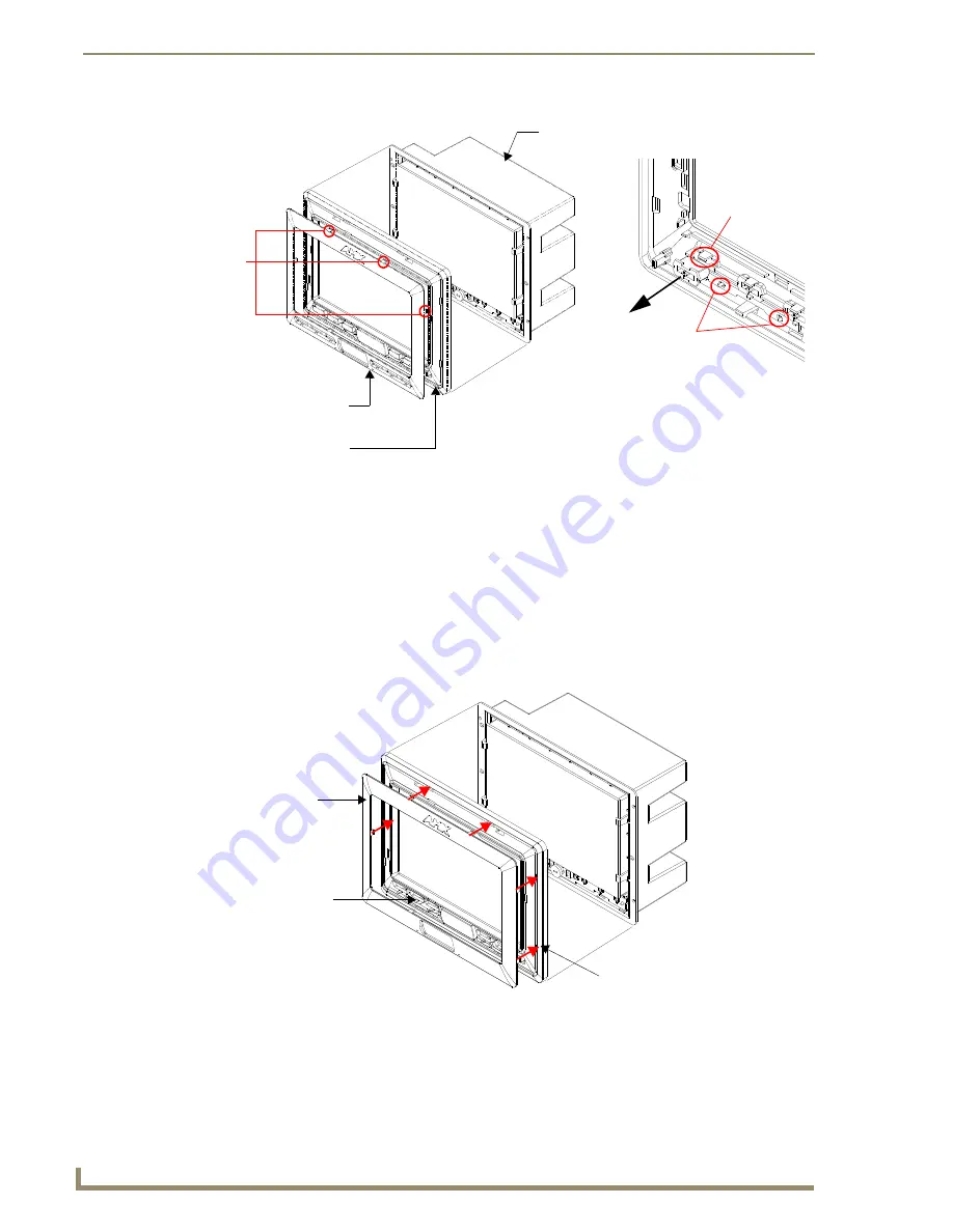
From along the internal surface of the Faceplate, remove the six buttons by gently bending each
Button latch up and pulling the button outwards.
6.
Remove the pair of clear light pipe strips by bending the two black light pipe latches inwards and
pulling out the strip.
7.
Grasp the No-Button Trim Ring on both sides and fit it into the groove along the outside surface of
the Faceplate (made available by the removal of the previous Trim Ring).
8.
Gently insert the Trim Ring latches into their corresponding openings on the outer surface of the
internal Faceplate (FIG. 33).
9.
Firmly press down around the No-Button Trim Ring until all of the latches are securely inserted into
their openings on the Faceplate, and the No-Button Trim Ring is securely fastened. Verify the
No-Button Trim Ring is firmly inserted onto the Faceplate and that there are no gaps between this
Trim Ring and the outer surface of the Faceplate.
FIG. 32
Removing the default Button Trim Ring
FIG. 33
Inserting the No-Button Trim Ring
Default Button Trim Ring
Trim
(with button openings)
B
Faceplate
CV7 Panel/enclosure
Ring
Latches
Button latch
Light Pipe latch
(black)
Button and Light Pipe removal
(showing the internal surface of Faceplate)
(outside surface shown)
No-Button Trim Ring
Faceplate (outer surface shown)
Hollow button openings
Summary of Contents for Modero CV7
Page 1: ...Operation Reference Guide Touch Panels NXD T CV7 7 Modero Touch Panel Last Revised 10 19 2011...
Page 42: ...CV7 Touch Panel Accessories 30 7 Modero Touch Panels...
Page 58: ...Installation 46 7 Modero Touch Panels...
Page 194: ...Programming 182 7 Modero Touch Panels...
Page 200: ...Appendix A 188 7 Modero Touch Panels...
Page 211: ...Appendix B Wireless Technology 199 7 Modero Touch Panels...
Page 212: ...Appendix B Wireless Technology 200 7 Modero Touch Panels...
Page 218: ...Troubleshooting 206 7 Modero Touch Panels...


