Overview DXLink Fiber
26
Instruction Manual – DXLink Fiber Transmitters and Receivers
Common Features/Functionality
This section covers HDCP compliance, the DIP switches, the USB port, and IR functionality.
HDCP Compliance
If the connected downstream sink is not HDCP compliant, then the HDMI output on the Receiver will not send the
signal. This does not affect additional displays the source may be routed to, i.e., HDCP compliant displays will still show
content from the source device even when the source device is also routed to non-compliant displays. Non-compliant
devices can be easily identified because they display an orange or dark red image to indicate the authentication process
failed.
DIP Switches
Tip:
For easiest access to the DIP switch toggles, we recommend setting them before installation.
Important:
When setting the DIP switch toggles, make sure any toggles that need to be ON are flipped
toward the AMX sticker.
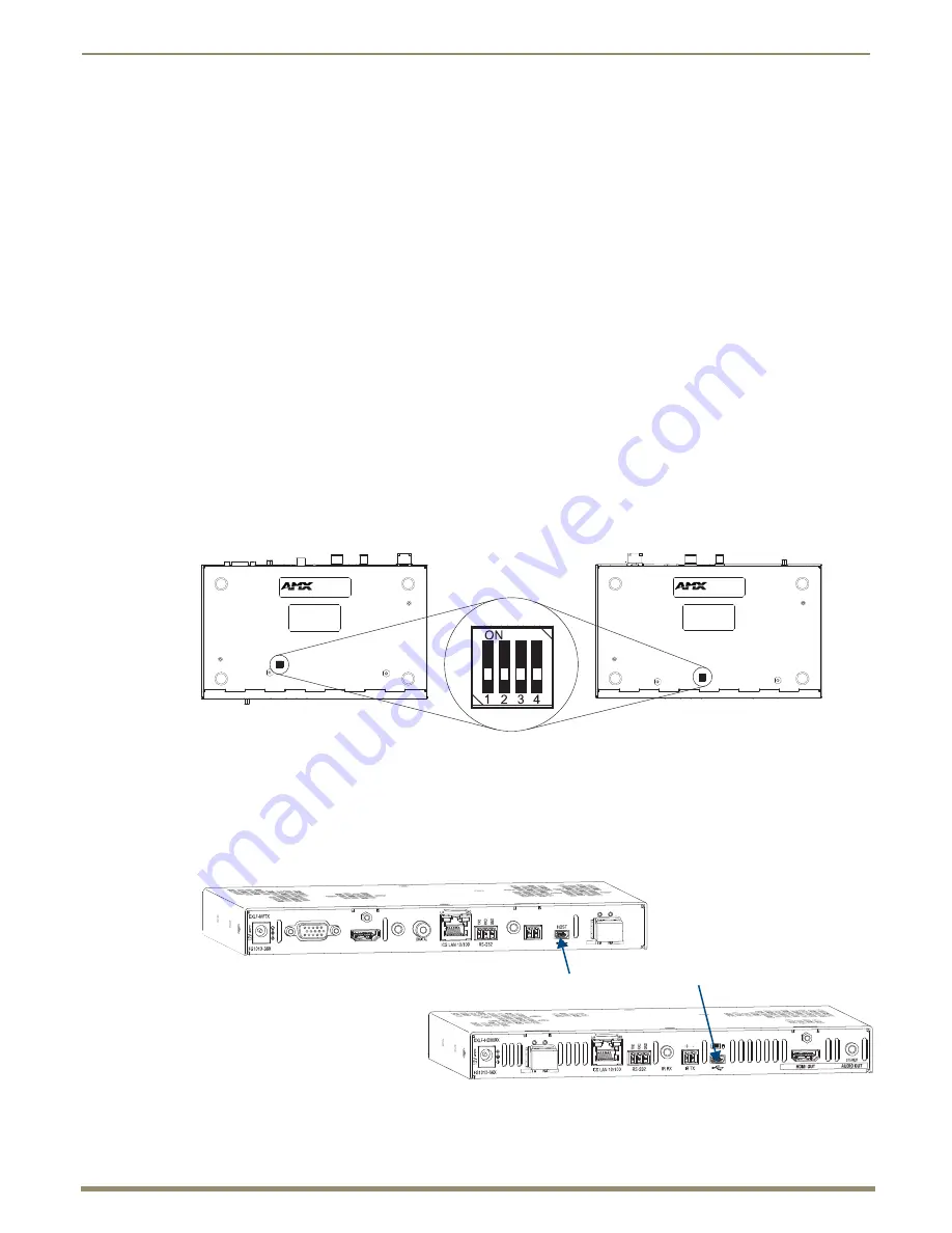
A four-toggle DIP switch is on the bottom of the DXLink Fiber Transmitters and Receivers.
#1 Toggle
is used for enabling/disabling the physical ICS LAN 10/100 port (page 44).
#2 Toggle
is used for setting the DXLink Fiber units to either automatically or manually determine the
DXLink Mode.
#3 Toggle
is used for enabling/disabling network connectivity of the DXLink Fiber unit to a connected
NetLinx Central Controller (used for IR ports, serial ports, and commands to the DXLink unit); page 45.
#4 Toggle
is used for placing Duplex units in Unidirectional Mode (page 56).
For complete information on setting DIP switches (including settings for common scenarios), see the section starting on
page 44.
USB Port (Rear)
FIG. 7
DIP switch location on DXLink Fiber units
FIG. 8
TX USB port – Host (top); RX USB port – Keyboard/Mouse (bottom)
DIP switch
Transmitter
Receiver
DXLink Fiber RX
USB port - Host
USB port - Keyboard/Mouse
DXLink Fiber TX


