1
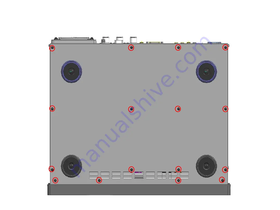
1. Remove 16 screws and open the bottom case.
Page 1: ...1 1 Remove 16 screws and open the bottom case...
Page 2: ...d with the RX 1 UNIT Coaxial 7 place FFC cable 2 place 01 marking Red 09 marking Black 10 Marking Red 12 marking Green 04 Note If you find it difficult to remove the coaxial cable we may provide you w...
Page 3: ...MAIN RX 1 UNIT SUB RX 2 UNIT MAIN RX 1 UNIT When installing the filters XF 128CN XF 128SN on the MAIN side RX 1 UNIT 3 Remove 6 Screws and remove the RX 1 UNIT from the chassis...
Page 4: ...128CN XF 128SN on the MAIN side RX 1 UNIT 4 Insert the filter in the specified position as shown below and solder it Cut the lead of the filters to 2 0 mm or less after installation Please install th...
Page 5: ...N XF 128SN on the MAIN side RX 1 UNIT 5 Re assemble the RX 1 UNIT to the chassis Fix and tighten the srews in order 1 2 3 4 For the rest screws there is no specific order MAIN RX 1 UNIT 5 0kgf cm 0 49...
Page 6: ...UNIT 6 Reconnect the cables to the connector of RX 1 UNIT Coaxial 7 place FFC cable 2 place Pass 4 coaxial cables under the lead clamp MAIN RX 1 UNIT 01 marking red 09 marking black 10 Marking red 12...
Page 7: ...les w VCT 101 FFC cable 1 cables w o VCT 101 2 cables w VCT 101 MAIN RX 1 UNIT SUB RX 2 UNIT 01 marking blue 09 marking black 10 marking red 12 marking none 04 02 MP marking none 03 MP marking green 0...
Page 8: ...SUB RX 2 UNIT SUB RX 2 UNIT MAIN RX 1 UNIT When installing the filters XF 129CN XF 129SN on the MAIN side RX 2 UNIT 3 Remove 6 Screws and remove the RX 2 UNIT from the chassis...
Page 9: ...rs XF 129CN XF 129SN on the MAIN side RX 2 UNIT 4 Insert the filter in the specified positions and solder it Cut the lead of filters to 2 0 mm or less after the installation Please install the filters...
Page 10: ...CN XF 129SN on the MAIN side RX 2 UNIT 5 Attach the RX 2 UNIT to the chassis Fix and tighten the screws in order 1 2 3 4 For the rest of screws there is no specific order SUB RX 2 UNIT 5 0kgf cm 0 49...
Page 11: ...connector of the RX 2 UNIT Coaxial 4 cables w o VCT 101 6 cables w VCT 101 FFC cable 1 cables w o VCT 101 2 cables w VCT 101 SUB RX 2 UNIT 01 marking blue 09 marking black 10 marking red 12 marking n...
Page 12: ...at all cable are within the top line of the chassis in order to avoid the cables be caught between chassis and case the positions you should specially make sure Insert the coaxial between the board an...
Page 13: ...Press to the front 13 8 Reassemble the bottom case with 16 screws Slightly pushing in the direction of the arrow tighten in order 1 2 3 4 For the rest of screws there are no specified order 8 0kgf cm...