Amphenol Temposonics R V Analog RDV Operation Manual Download Page 22

Temposonics

® 

R-Series 

V

 Analog

Operation Manual

I 22 I

Mounting the RFV

 1. RFV-B

• Insert the flexible sensor rod in a support tube.
• Mount the sensor electronics housing by means of 3 non-

magnetic socket head screws M4×59. Fastening torque: 1.4 Nm 
(Fig. 16). Secure the screws, e.g. using Loctite 243, before re-
installing. 
Recommendation: Seal the sensor via flange.

 2. RFV-B with pressure rod HD/HL/HP or HFP profile (see 

“Frequently ordered accessories”) 


Advantage: The flexible sensor rod is inserted in a support tube.
• Mount the sensor electronics housing by means of 3 non-

magnetic socket head screws M4×59. Fastening torque: 1.4 Nm 
(Fig. 16). Secure the screws, e.g. using Loctite 243, before re-
installing.

• Installation details: see below

 3. RFV-M/-S

• Insert the flexible sensor rod in a support tube.
• Mount the sensor via flange.
• Installation details: see below
• Please note that liquid can enter the sensor between the thread 

and the flexible rod.

Installation of RFV with threaded flange »M«, »S«

Fix the sensor rod via threaded flange M18×1.5-6g or ¾"-16 UNF-3A. 
Note the fastening torque of
RFV-M: 65 Nm
RFV-S:  50 Nm

Installation of an RFV sensor with pressure rod HD/HL/HP in a fluid 
cylinder

The rod-style version has been developed for direct stroke measure-
ment in a fluid cylinder. Mount the sensor via threaded flange or a hex 
nut.
•  Mounted on the face of the piston, the position magnet travels over 

the rod without touching it and indicates the exact position through 
the rod wall – independent of the hydraulic fluid.

•  The pressure resistant sensor rod is installed into a bore in the 

piston rod.

•  The base unit is mounted by means of only 3 screws. It is the 

only part that needs to be replaced if servicing is required, i.e. the 
hydraulic circuit remains closed. For more information see chapter 
“4.7 Replacement of base unit” on page 34.

•  Note the fastening torque of  

HD: 

65 Nm 

HL: 

50 Nm 

HP: 

55 Nm

•  Seat the flange contact surface completely on the cylinder mounting 

surface.

•  The cylinder manufacturer determines the pressure-resistant gasket 

(copper gasket, O-ring, etc.).

•  The position magnet should not grind on the sensor rod.
•  The piston rod drilling for RFV sensors with pressure rod (outer 

diameter 12.7 mm (0.5 in.)) is ≥ 16 mm (≥ 0.63 in.). The borehole 
depends on the pressure and piston speed.

•  Adhere to the information relating to operating pressure.
•  Protect the sensor rod against wear.

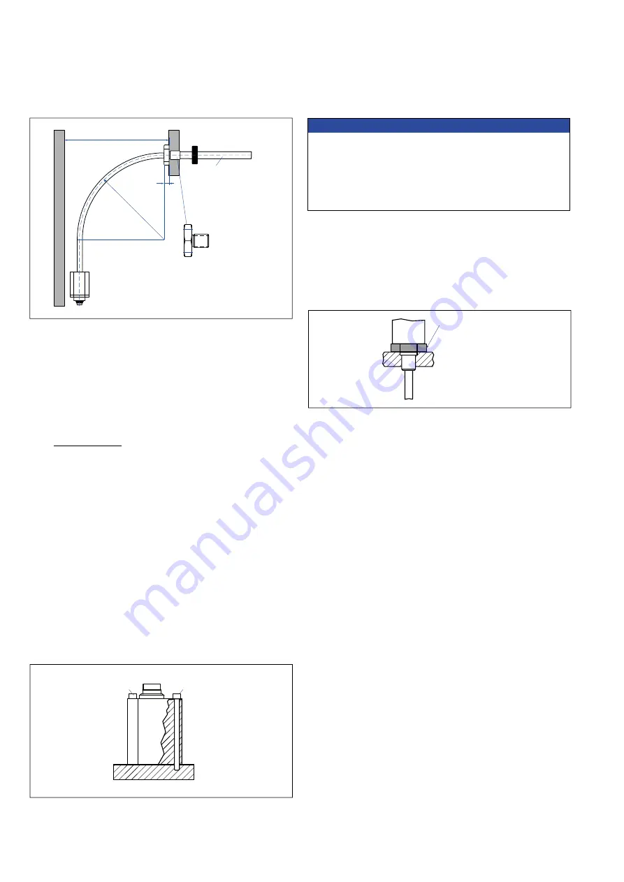
500 (20) recommended

≥ 300 (≥ 11.81)

Position magnet

10

(0.4)

A/F 46

Flange M18×1.5-6g

¾"-16 UNF-3A

Customized support tube

required e.g. Ø 12.7 × 1.65 

(Ø 0.5 × 0.65),

inside Ø 9.4 (Ø 0.37), 

non-magnetic

R > 250

(R > 9.84)

Fastening torque:

RFV-M: 65 Nm 

RFV-S: 50 Nm 

HD: 65 Nm 

HL: 50 Nm 

HP: 55 Nm

Socket head screw

 M4×59

Socket head screw 

M4×59

Fastening torque of socket head screw M4×59: 1.4 Nm

Fig. 15: Clearances for installation and handling

Fig. 16: Mounting with socket head screws M4×59 

Fig. 17: Mounting example of threaded flange

NOTICE

To fulfill the requirements of EMC standards for emission and 
immunity the following points are necessary:
•  The sensor electronics housing has to be connected to machine 

ground (Fig. 45).

•  Embed the flexible sensor element in an appropriately shielded 

environment, e.g. in a pressure rod HD/HL/HP.

Controlling design dimensions are in millimeters and measurements in ( ) are in inches

Summary of Contents for Temposonics R V Analog RDV

Page 1: ...Magnetostrictive Linear Position Sensors Operation Manual R Series V Analog GENERATION V THE NEW...

Page 2: ...FV 20 4 5 Installation and design of Temposonics RDV 24 4 6 Magnet installation 30 4 7 Replacement of base unit 34 4 8 Electrical connection 35 4 9 Frequently ordered accessories for sensor model RP5...

Page 3: ...ables are damaged Short circuit the sensor can be damaged sensor does not respond Spacers are missing installed in a wrong order Error in position measurement Wrong connection of ground shield Signal...

Page 4: ...ion hazardous areas The sensors are not suitable for operation in explosion hazardous areas 2 See also applicable Temposonics terms of sales and delivery on www temposonics com 2 5 Warranty Temposonic...

Page 5: ...sition s 1 2 magnet s f Connection type Connector D 3 4 M12 male connector 5 pin D 6 0 M16 male connector 6 pin Angled cable outlet E X X XX m ft PVC cable part no 530 032 E01 E30 1 30 m 3 99 ft See F...

Page 6: ...e when Function is 2 or 3 For metric stroke lengths encode speed or velocity in m s for the values 0 01 to 9 99 m s 001 999 For US customary stroke lengths encode speed or velo city in inches s for th...

Page 7: ...0 1 in increments e Number of magnets 0 X 01 02 Position s 1 2 magnet s f Connection type Connector D 3 4 M12 male connector 5 pin D 6 0 M16 male connector 6 pin Angled cable outlet E X X XX m ft PVC...

Page 8: ...on 10 10 VDC for velocity l Max speed or velocity value optional use when Function is 2 or 3 For metric stroke lengths encode speed or velocity in m s for the values 0 01 to 9 99 m s 001 999 For US cu...

Page 9: ...ntly ordered accessories for cable specifications G X X XX m ft FEP cable part no 530 157 G01 G30 1 30 m 3 99 ft See Frequently ordered accessories for cable specifications L X X XX m ft PUR cable par...

Page 10: ...ion 10 10 VDC for velocity l Max speed or velocity value optional use when Function is 2 or 3 For metric stroke lengths encode speed or velocity in m s for the values 0 01 to 9 99 m s 001 999 For US c...

Page 11: ...5 mm 0 1 in increments e Number of magnets 0 X 01 02 Position s 1 2 magnet s f Connection type Connector D 3 4 M12 male connector 5 pin D 6 0 M16 male connector 6 pin Angled cable outlet E X X XX m ft...

Page 12: ...ion 10 10 VDC for velocity l Max speed or velocity value optional use when Function is 2 or 3 For metric stroke lengths encode speed or velocity in m s for the values 0 01 to 9 99 m s 001 999 For US c...

Page 13: ...20 in additional stroke length RH5 rod sensor RH5 B Base unit without flange rod assembly 3 socket screws M4 59 RH5 J M S T Sensor O ring RFV flexible rod sensor RFV B Base unit without flange rod as...

Page 14: ...his creates a momentary radial magnetic field and torsional strain on the waveguide The momentary interaction of the magnetic fields releases a torsional strain pulse that propagates the length of the...

Page 15: ...5 6350 1 250 Dead zone 66 71 2 6 2 8 48 1 89 9 5 0 37 35 6 1 4 50 1 97 68 2 68 2 0 08 45 1 77 28 1 1 5 3 0 21 12 0 47 Start position RP5 M example Connection type EXX GXX LXX UXX angled cable outlet M...

Page 16: ...hese clamps are delivered with the sensor and must be distributed over the profile at regular distances For fastening use M5 20 screws to DIN 6912 that should be tightened with a fastening torque of 5...

Page 17: ...2 01 Magnet Stroke length 5000 mm 196 9 in Dead zone 63 5 66 2 5 2 6 10 0 13 0 39 0 01 2 5 0 1 25 0 98 11 5 0 45 A F 44 5 A F 1 75 51 3 2 02 RH5 T A V RH5 with threaded flange 16 UNF 3A with raised fa...

Page 18: ...flange J M22 1 5 6g Magnet 12 7 0 13 0 5 0 01 Dead zone 73 6 2 9 13 0 51 RH5 B A V RH5 base unit only for replacement example Connection type D60 connector outlet 48 1 89 Sensor electronics housing 58...

Page 19: ...8 Mounting example of threaded flange Fig 9 Sensor in cylinder In the case of threaded flange M18 1 5 6g or M22 1 5 6g provide a screw hole based on ISO 6149 1 Fig 11 See ISO 6149 1 for fur ther infor...

Page 20: ...7 3 4 6 1 3 6 48 1 89 RFV M S RFV with threaded flange M18 1 5 6g or 16 UNF 3A example Connection type D34 connector outlet Magnet b 13 0 51 Not exible 97 3 82 Sensor electronics housing 58 2 28 10 0...

Page 21: ...0 59 in 30 mm 1 18 in 15 mm 0 59 in 45 mm 1 77 in 94 mm 3 70 in 100 mm 3 94 in 120 mm 4 72 in 140 mm 5 51 in Note Tolerance of total length has no in uence on the stroke length Sensor electronics hous...

Page 22: ...stant sensor rod is installed into a bore in the piston rod The base unit is mounted by means of only 3 screws It is the only part that needs to be replaced if servicing is required i e the hydraulic...

Page 23: ...FV B with three screws to the existing hole pattern with two screws Fasten the adapter plate to the existing hole pattern using the two M4 6 A F 2 5 hexagon socket screws with a tightening torque of 1...

Page 24: ...2 24 7 0 97 7 7 0 3 24 7 0 97 6 2 0 24 19 0 75 26 2 1 03 50 1 97 48 1 89 45 1 77 RDV with side cable entry example Connection type D60 connector outlet Recommendation Use M6 45 ISO 4762 screws Fasteni...

Page 25: ...th bottom cable entry example Connection type HXX RXX straight cable outlet 58 2 28 25 0 98 45 1 77 45 1 77 48 1 89 RDV with side cable entry example Connection type TXX straight cable outlet x 58 2 2...

Page 26: ...23 6 Threaded flange M M18 1 5 6g Magnet 4 5 0 18 Cable for bottom cable entry Cable for side cable entry A F 24 Threaded flange T for bottom or side cable entry Threaded flange T 16 UNF 3A 10 0 13 0...

Page 27: ...otect the sensor rod against wear Fig 23 Mounting example of threaded flange C D M T Fig 24 Possibilities of sealing NOTICE NOTICE Mount the sensor as follows 1 Mount the flange with sensor rod 2 Moun...

Page 28: ...lating to operating pressure Protect the sensor rod against wear Fig 26 Example of mounting detail Shoulder screw 8 M6 ISO 7379 with internal hexagon Fig 27 Pressure fit flange S details Notice for me...

Page 29: ...Back up ring part no 560 629 Magnet Fig 29 Mounting example of pressure fit flange S and sensor electronics with side cable entry Fig 30 Mounting of RDV s sensor electronics housing example of bottom...

Page 30: ...mm 0 6 in Fig 34 If no other option exists and magnetic material is used observe the specified dimensions Fig 34 Magnet mounting with magnetic material When using magnetic material the dimensions of...

Page 31: ...ng Stroke length 5000 mm 196 9 in End position 68 5 73 5 2 7 2 9 Start position 25 5 1 RH5 with ring magnet U magnet Sensor electronics housing Reference edge of mounting Start position 51 2 01 End po...

Page 32: ...5 2 6 Stroke length 5000 mm 196 9 in RDV C D with ring magnet U magnet Reference edge of mounting Start position 51 2 01 Stroke length 5000 mm 196 9 in RDV S with block magnet Reference edge of mounti...

Page 33: ...ent RH5 RP5 RFV RDV NOTICE Use magnets of the same type for multiposition measurement Do not go below a minimal distance of 75 mm 3 in between the magnets for differential measurement Contact Temposon...

Page 34: ...the hydraulic circuit This also applies to the RFV B sensor which is installed in the optional HD HL and HP pressure rod 3 Insert the new base unit Install the ground lug on a screw Tighten the screws...

Page 35: ...ing leads with large cross section or use cables with separate double shielding and connect only one end of the shield Use only stabilized power supplies in compliance with the specified electrical ra...

Page 36: ...y magnet 1 or temperature inside the sensor electronics housing GN Signal Ground BN 12 30 VDC 20 WH DC Ground 0 V order dependent For cable type TXX the extra red blue wires are not used Straight cabl...

Page 37: ...Approx 25 g Operating temperature 40 85 C 40 185 F Position magnets Mounting accessories 32 8 1 29 23 8 0 94 13 5 0 53 4 3 0 17 60 140 3 0 12 7 9 0 31 19 5 0 77 1 5 0 06 33 1 3 14 0 55 20 5 0 81 14 9...

Page 38: ...0 17 3 2 0 13 15 3 0 6 2 2 0 09 16 4 0 65 2 2 0 09 Block magnet L Part no 403 448 Magnet spacer Part no 400 633 O ring for threaded flange M18 1 5 6g Part no 401 133 O ring for threaded flange 16 UNF...

Page 39: ...pprox 13 g Surface pressure Max 20 N mm2 Operating temperature 40 100 C 40 212 F Material PA 66 GF30 magnets compound filled Weight Approx 26 g Surface pressure 20 N mm2 Fastening torque for M4 screws...

Page 40: ...le with flange HFP length mm XXXXX M HFP length in XXXX X U Pressure rod 12 7 mm 0 5 in Length 100 7500 mm 4 295 in Operating pressure 350 bar 5076 psi Material flange Stainless steel 1 4305 AISI 303...

Page 41: ...ization Part no 253620 Marked version for sensors with inter nal linearization Part no 253 621 Magnet spacer O rings 14 3 0 56 23 8 0 94 31 8 1 25 4 3 0 17 3 2 0 13 15 3 0 6 2 2 0 09 16 4 0 65 2 2 0 0...

Page 42: ...16 0 63 12 0 47 3 2 0 13 3 2 0 13 M3 fastening screws 6 Fixing clip Part no 561 481 Application Used to secure sensor rods 10 mm 0 39 in when using an U magnet or block magnet Material Brass non magn...

Page 43: ...Ni Termination Screw max 0 75 mm Contact insert CuZn Cable 5 8 mm 0 2 0 31 in Wire 0 75 mm2 18 AWG Operating temperature 25 85 C 13 185 F Ingress protection IP67 correctly fitted Fastening torque 0 4...

Page 44: ...t no 253 124 Cabinet programmer for analog output Part no 253 408 TempoLink kit for Temposonics R Series V Part no TL 1 0 AD60 for D60 Part no TL 1 0 AS00 for cable outlet Part no TL 1 0 AD34 for D34...

Page 45: ...e length and yy unit in centimeters CM or feet FT PUR cable part no 530 052 with M16 female connector straight part no 370 423 Order code K2 A 370423 xxxxyy 530052 0 where xxxx cable length and yy uni...

Page 46: ...l channel sensor for 2 magnets 0 VDC 10 VDC 5 2 Introduction Temposonics R Series V Analog sensors are pre configured at the factory by the model number ordering code For many applications normal sens...

Page 47: ...t in an uncontrolled way when switching on 4 Ensure that the sensor is ready and in operation mode after switching on The status LED lights permanently green 5 Check the preset span start and end valu...

Page 48: ...rrel connector of the adapter cable to the connection point labeled OUTPUT SENSOR on the TempoLink smart assistant Fig 54 NOTICE When disconnecting the power supply of the sensor possibly error messag...

Page 49: ...rding to the connector wiring in Fig 60 Fig 61 There are two ways to connect the TempoLink smart assistant to a power supply 1 Connection via the plug in power supply with plug adapters Attach the plu...

Page 50: ...rt labeled USB on the TempoLink smart assistant Fig 63 2 Next connect the USB type A connector to a free USB port of the computer The USB connection simulates a network card In the folder network conn...

Page 51: ...s information about the sensor status Sensor Info Includes information about the connected sensor Parameters Includes information about the operational settings of the connected sensor Interface Inclu...

Page 52: ...ntering Analog command mode NOTICE If the sensor is in command mode the sensor may cease to output valid magnet position values 2 After entry into command mode the connection icon in the top right wil...

Page 53: ...to allow adjusting the values For this example the output range is changed to 0 20 mA You can change the values via the drop down menu Confirm your changes by clicking the SUBMIT button Fig 70 Adjusti...

Page 54: ...box is 19 9 mA Confirm your changes by clicking the SUBMIT button Fig 72 Adjusting the output value for set point two 6 The last setting for channel one output is for the error output value For this e...

Page 55: ...for set point one start of stroke and set point two end of stroke Click on Read Magnet to retrieve the currently measured position value for magnet 1 Confirm your changes by clicking the SUBMIT button...

Page 56: ...to exit the command mode and to transfer the changed parameters to the sensor Fig 77 If you click the button CANCEL the changed parameters are not transferred to the sensor The sensor returns to the...

Page 57: ...1 Magnet position Active measuring range 1 Magnet sensor Output 1 position 0 100 2 Magnets Active measuring range min 76 mm 0 100 2 Magnet sensor Output1 Position magnet 1 Output 2 Position magnet 2...

Page 58: ...The programming mode can be activated without any additional service tool at any time Normal function 1 Slide the Program Run switch to run all sensor leads are connected to the controller a The senso...

Page 59: ...y Temposonics or a repair facility explicitly authorized by Temposonics For return see chapter 2 6 Return on page 4 6 4 List of spare parts No spare parts are available for this sensor 6 5 Transport a...

Page 60: ...olution 16 bit minimum 0 01 mm s Operating conditions Operating temperature 40 85 C 40 185 F Humidity 90 relative humidity no condensation Ingress protection IP67 connectors correctly fitted IP68 3 m...

Page 61: ...onnection type 1 M16 male connectors 6 pin 1 M12 male connector 5 pin or cable outlet Operating voltage 12 30 VDC 20 9 6 36 VDC Power consumption 3 25 W Dielectric strength 500 VDC DC ground to machin...

Page 62: ...rotection IP67 connectors correctly fitted IP68 3 m 3 d for cable outlet Shock test 150 g 11 ms IEC standard 60068 2 27 Vibration test 30 g 10 2000 Hz IEC standard 60068 2 6 excluding resonant frequen...

Page 63: ...onnection type 1 M16 male connector 6 pin 1 M12 male connector 5 pin or cable outlet Operating voltage 12 30 VDC 20 9 6 36 VDC Power consumption 3 25 W Dielectric strength 500 VDC DC ground to machine...

Page 64: ...midity 90 relative humidity no condensation Ingress protection IP30 IP65 rating only for professional mounted guide pipe and if mating connectors are correctly fitted Shock test 100 g 6 ms IEC standar...

Page 65: ...nnection type 1 M16 male connector 6 pin or 1 M12 male connector 5 pin or cable outlet Operating voltage 12 30 VDC 20 9 6 36 VDC Power consumption 3 25 W Dielectric strength 500 VDC DC ground to machi...

Page 66: ...easuring rod with connecting cable for side cable entry IP65 Measuring rod with single wires and flat connector with bottom cable entry IP30 Shock test 100 g 11 ms IEC standard 60068 2 27 Vibration te...

Page 67: ...al drawings on page 24 page 25 and page 26 Electrical connection Connection type 1 M16 male connector 6 pin 1 M12 male connector 5 pin or cable outlet Operating voltage 12 30 VDC 20 9 6 36 VDC Power c...

Page 68: ...tion of malfunction Corporate information Company ________________________________________________ Address ________________________________________________ ____________________________________________...

Page 69: ...000 See Detail C 3 4 16 UNF 2B Thread See Notes 3 And 4 32 in 32 in 125 in B 1 105 in Minimum Full Thread Depth 0 875 in dia 0 015 0 000 0 769 in dia 0 015 0 000 0 500 in dia 0 005 in dia FIM A 45 5 1...

Page 70: ...hen enabled this mode allows the position output values to continue to increase or decrease when the magnet travels beyond the active stroke range R Resolution The sensor precisely measures time to pr...

Page 71: ...46 70 29 91 281 E mail info sca temposonics com CHINA Branch Office Phone 86 21 2415 1000 2415 1001 E mail info cn temposonics com JAPAN Branch Office Phone 81 3 6416 1063 E mail info jp temposonics c...

Reviews: