MRO 3 & 4 MANUAL
21
98-0140
Rev. F
b.
Press and hold the LEFT ARROW key and then, press the RIGHT ARROW key.
This will access the DISINFECT MODE. The controller display will show
DISINFECT ENABLED and the keys can be released.
c.
Press and hold the ENTER key to turn on the Disinfect Draw function and THE
DISPLAY WILL READ
DISINFECT ENABLED DRAW
. Continue to hold the
ENTER key, until all of the water is drawn in and you begin to see air bubbles in
the draw tube. This will flush out any residual PAA left in the injection plumbing.
d.
Disconnect the PAA Container PAA tubing from the PAA connection on the front
of the MRO.
24.
Turn on the MRO by pressing the POWER key. Open the REJECT VALVE to allow
full flow of REJECT WATER. Record the Start time on the Startup Log. Allow the
machine to run at this setting for at least 15 minutes.
25.
After the required soak time is achieved in the DISINFECT mode, press the ALARM
SILENCE/RESET key to exit the DISINFECT Mode and verify that the MRO is off
(STANDBY).
26.
DO NOT reconnect the PRODUCT WATER hose (if disconnected).
WARNING:
Do not connect to any dialysis machine at this time. The water quality
may register good, but it is possible that some residual PAA disinfecting
solution is still in the system. Less than 3 PPM of the disinfecting
solution must be present before the system is reconnected to any dialysis
machine.
27.
After rinsing with the REJECT VALVE allowing full flow for at least 15 minutes, turn the
REJECT VALVE clockwise until the REJECT flow is approximately equal to the
PRODUCT flow (normal operation reject flow). Allow the MRO to run for 15 more
minutes.
28.
After the first 30 minutes, repeat 15 more minutes of full flow through the REJECT
VALVE + 15 more minutes of operation a normal operation reject flow. Begin to test
for the presence of PAA with residual test strips (
IBT Renal Check PX Test Strips
(P/N 97PX20501)
at all water outlet points (if connected to a loop).
28a. If the MRO is not connected to a loop, periodically test for the presence of residual
PAA at the ends of the REJECT HOSE AND PRODUCT WATER hose as the water
exits the hoses into the sink until less than 3PPM of PAA is detected by the residual
test strips.
28b. If the MRO is connected to a closed end loop dumping through a relief valve to drain,
periodically test for the presence of residual PAA at each water use outlet, and where
the relief valve is dumping to drain until less than 3 PPM of PAA is detected by the
residual test strips.
28c. If the MRO is connected to a loop that is being recirculated back through a Product
Summary of Contents for MRO3
Page 8: ...MRO 3 4 MANUAL 5 98 0140 Rev F SECTION 3 COMPONENTS AND SCHEMATICS 3 1 EXTERNAL FRONT VIEW...
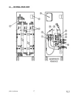
Page 10: ...MRO 3 4 MANUAL 7 98 0140 Rev F 3 2 INTERNAL REAR VIEW...
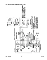
Page 12: ...MRO 3 4 MANUAL 9 98 0140 Rev F 3 3 ELECTRICAL DIAGRAM MRO3 MRO4...
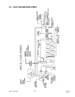
Page 13: ...MRO 3 4 MANUAL 10 98 0140 Rev F 3 4 FLUID DIAGRAM MRO3 MRO4...
Page 34: ...MRO 3 4 MANUAL 31 98 0140 Rev F FIGURE 6 2...
Page 35: ...MRO 3 4 MANUAL 32 98 0140 Rev F FIGURE 6 3...
Page 52: ...MRO 3 4 MANUAL 49 98 0140 Rev F SECTION 11 MRO3 4 SPARE PARTS LISTING...

