MRO 3 & 4 MANUAL
14
98-0140
Rev. F
4.3
INITIAL STARTUP
WARNING: This Reverse Osmosis System (RO) contains a preservative solution to
prevent microbiological growth and freezing. Discard all product water
for at least two hours of operation before placing the RO in service.
1. Lock the two front casters so that the MRO will remain stationary during startup.
2. Remove the protective covers from the PRODUCT WATER, REJECT WATER TO DRAIN
and INCOMING TAP WATER barbed fittings on the side of the MRO.
3. Slide the hose clamps over the hoses that were provided in the installation package for
holding the 3 hoses in place on the MRO.
4. Slip the INCOMING TAP WATER, PRODUCT WATER and REJECT WATER TO DRAIN
hoses over the appropriate barbed fitting, then secure each with a hose clamp.
CAUTION:
To assure proper assembly, hoses MUST be fully inserted over the barbed
area and a little beyond for the clamp to hold in the “necked-down” area
of the barbed fitting.
5. Connect the MRO INCOMING TAP
WATER hose to the potable water
supply using the Incoming Tap Water
hose and fittings supplied. If blending
both warm and cold water to improve
product flow rate, do not exceed 90° F
(33° C).
6. The REJECT WATER TO DRAIN hose
coming out of the MRO system is for
reject water. The water from this hose
will always go down a sink. Leave at
least a 2" air gap between the hose
and the drain to prevent contamination
or siphoning.
7. The PRODUCT WATER hose should also be secured to the sink until the start-up flush
and initial disinfection cycle are completed, and the water quality is in the good range
(below the conductivity setpoint, and not in alarm).
8. Open the access cover and make sure the “CIP” switch is in the “OFF” position.
9. Plug the power cord into the appropriate receptacle.
10. The high voltage power cord must be connected to an appropriately sized disconnect for
the voltage and the phases used. Connection to a wall disconnect must be done by a
qualified electrician.
11. If a plug on the high voltage power cord has been installed, there must be a matching
Summary of Contents for MRO3
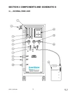
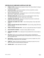
Page 8: ...MRO 3 4 MANUAL 5 98 0140 Rev F SECTION 3 COMPONENTS AND SCHEMATICS 3 1 EXTERNAL FRONT VIEW...
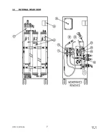
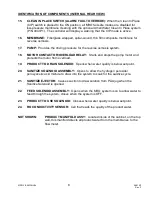
Page 10: ...MRO 3 4 MANUAL 7 98 0140 Rev F 3 2 INTERNAL REAR VIEW...
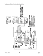
Page 12: ...MRO 3 4 MANUAL 9 98 0140 Rev F 3 3 ELECTRICAL DIAGRAM MRO3 MRO4...
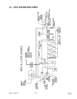
Page 13: ...MRO 3 4 MANUAL 10 98 0140 Rev F 3 4 FLUID DIAGRAM MRO3 MRO4...
Page 34: ...MRO 3 4 MANUAL 31 98 0140 Rev F FIGURE 6 2...
Page 35: ...MRO 3 4 MANUAL 32 98 0140 Rev F FIGURE 6 3...
Page 52: ...MRO 3 4 MANUAL 49 98 0140 Rev F SECTION 11 MRO3 4 SPARE PARTS LISTING...

