MRO 3 & 4 MANUAL
16
98-0140
Rev. F
CAUTION:
Although the water treatment system may produce water of sufficient quality
to meet the requirements of AAMI standards, distribution of the water may
degrade its quality to the point where it no longer meets the requirements of
this standard. AmeriWater offers information about ultra pure water piping
to prevent the degradation of product water in a water loop or central
system.
4.4
SYSTEM SHUTDOWN
Ordinarily, an MRO3 or 4 is connected to a water use system that is used continually or very
frequently. Therefore, frequent shutting down is not necessary. Typically, the MRO is
connected to a Direct Feed Loop or Storage Tank of a Central System. If so, the MRO
should be cycled using the “Membrane Flush” feature in the controller of the MRO. This will
allow an MRO connected to a Direct Feed Loop while in STANDBY to start and circulate
Product Water through the loop at some predetermined frequency for a predetermined
amount of time (every 4 to 6 hours for 15 minutes, for example). This allows the water to be
“freshened” in the MRO and loop. When the MRO is connected to the storage tank of a
central system, the MRO shall remain in OPERATION. When the “Membrane Flush” feature
is active, the MRO will cycle on some predetermine frequency to send the Product Water
through the “Divert to Drain” feature of the MRO to the drain. This will only occur when the
“Tank Full High” limit switch indicates that the tank is full for a long period of time (usually
around 6 hours) since the last use of the MRO
If the MRO must be shut down for an extended period, however, use the following
instructions:
1. Before turning off the MRO by pressing the POWER key, turn the REJECT VALVE
counter clockwise to allow a full-flow “FLUSH” for 5 minutes. This will flush the
concentrate out of the system.
2. Press the POWER key (the display will show STANDBY).
3. Turn off the potable tap water supply to the system.
4. Disconnect the PRODUCT WATER hose from the Direct Feed Loop or Storage tank,
and the INCOMING TAP WATER hose from the potable tap water supply. The hoses
may be connected together to prevent dirt from entering the hoses.
5. Remove the REJECT WATER TO DRAIN hose from the sink. The hoses and power
cord may be secured by the hose strap on the side of the MRO for storage or transport
of the MRO.
6. See Initial Startup in Section 4 for instructions before the next use.
The system will
need to be disinfected before the next use if it sits unused for 1 or more days, or
in accordance to the guidelines of your medical facility director.
7. When transporting the MRO, push or pull the system carefully, because it may be top-
heavy and may easily tip over.
Summary of Contents for MRO3
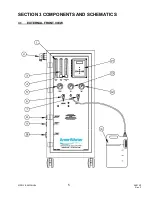
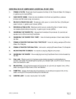
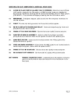
Page 8: ...MRO 3 4 MANUAL 5 98 0140 Rev F SECTION 3 COMPONENTS AND SCHEMATICS 3 1 EXTERNAL FRONT VIEW...
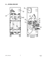
Page 10: ...MRO 3 4 MANUAL 7 98 0140 Rev F 3 2 INTERNAL REAR VIEW...
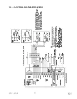
Page 12: ...MRO 3 4 MANUAL 9 98 0140 Rev F 3 3 ELECTRICAL DIAGRAM MRO3 MRO4...
Page 13: ...MRO 3 4 MANUAL 10 98 0140 Rev F 3 4 FLUID DIAGRAM MRO3 MRO4...
Page 34: ...MRO 3 4 MANUAL 31 98 0140 Rev F FIGURE 6 2...
Page 35: ...MRO 3 4 MANUAL 32 98 0140 Rev F FIGURE 6 3...
Page 52: ...MRO 3 4 MANUAL 49 98 0140 Rev F SECTION 11 MRO3 4 SPARE PARTS LISTING...

