R
EV
9
79
A
MERICAN
M
AGNETICS
, I
NC
.
O
PERATION
: S
ETUP
S
UBMENU
D
ESCRIPTIONS
: L
OAD
S
UBMENU
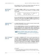
The
Manual
stability mode provides complete control over the
control gain based on a numerical entry for the stability setting.
The Manual mode
requires
the operator to enter a stability setting
per the description on page 79.
The
Test
stability mode is designed to allow the user to test the
function of the system with
the power leads to the magnet
shorted together at the magnet connection point.
This allows
ramping of the system to verify proper setup. The Test mode
should only be used with shorted magnet power leads for
checkout purposes.
NOTE
It is important that the full length of the power leads to the
magnet be connected during the
Test
mode since the leads
provide some resistive load (albeit in the milliohm range) for the
power supply. The output current of a truly shorted supply output
(i.e. zero resistance load) is very difficult to control in voltage
mode and may be unstable.
S
TABILITY
S
ETTING
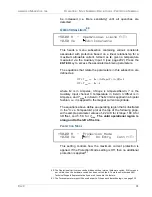
The stability setting is specified in percent and controls the
transient response and stability of the system. The value can be
set by using either the numeric keypad as described on page 54
or the fine adjust knob (on page 55). The valid range is from 0.0
to 100.0%. The default value is 0.0% unless preset by AMI to
match a specific superconducting magnet.
S
TABILITY
S
ETTING
FOR
M
AGNETS
WITHOUT
A
P
ERSISTENT
S
WITCH
33
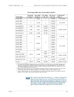
Superconducting magnets
without
a persistent switch
34
require a
specific Model 430 Programmer stability setting based on the
magnet inductance as follows:
For magnet inductance
≤
100 Henries (H):
Stability Setting = (100 - H)
For magnet inductance
>
100 Henries:
Stability Setting = 0
33. For maximum Vm stability, you may opt to use a stabilizing resistor instead. See page 43 for
details. For stabilizing resistor configurations, use the Stability Setting plot specified in the
next section for magnets with a persistent switch.
34. Effective with Model 430 firmware version 1.62 or later, magnets without a switch may be
operated without a stabilizing resistor present using the Stability Settings specified.
0.00 A — Stability Setting (%)
+0.50 Vs
0.0
Summary of Contents for 430
Page 2: ......
Page 16: ...XVI REV 9 AMERICAN MAGNETICS INC FOREWORD SAFETY SUMMARY ...
Page 28: ...12 REV 9 AMERICAN MAGNETICS INC INTRODUCTION OPERATING CHARACTERISTICS ...
Page 64: ...48 REV 9 AMERICAN MAGNETICS INC INSTALLATION POWER UP AND TEST PROCEDURE ...
Page 208: ...192 REV 9 AMERICAN MAGNETICS INC SERVICE RETURN AUTHORIZATION ...
Page 248: ...232 REV 9 AMERICAN MAGNETICS INC APPENDIX SHORT SAMPLE MODE ...


