


70
R
EV
9
A
MERICAN
M
AGNETICS
, I
NC
.
O
PERATION
: LED I
NDICATORS
LED I
NDICATORS
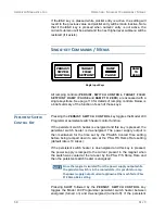
The Model 430 Programmer has six front panel LED indicators. See the
front panel illustration and table on page 4 for the location of these
indicators.
P
OWER
-
ON
I
NDICATOR
The green power-on LED indicates that the Model 430 Programmer is
powered on.
M
AGNET
S
TATUS
I
NDICATORS
Four LEDs are grouped together to show the magnet status.
F
IELD
A
T
T
ARGET
I
NDICATOR
The green
FIELD AT TARGET
LED indicates that the current is
at the target value. If the magnet is not in persistent mode
(persistent switch heater is on), then this is an indication that the
magnet field has reached the target value. If the magnet is
already in persistent mode, then this is an indication that the
current being supplied to the magnet system has reached the
target value.
M
AGNET
I
N
P
ERSISTENT
M
ODE
I
NDICATOR
CAUTION
If the Model 430 Programmer power is turned off while the
persistent switch is heated, persistent switch heating will be
lost and the magnet will enter persistent mode. The Model
430 will not have a record of that event. Therefore the
MAGNET IN PERSISTENT MODE
LED state will be
incorrect (remain OFF) when the Model 430 Programmer
power is restored.
Magnet Status LED Indicators
FIELD AT TARGET
MAGNET IN PERSISTENT MODE
MAGNET QUENCH
CURRENT LEADS ENERGIZED
Summary of Contents for 430
Page 2: ......
Page 16: ...XVI REV 9 AMERICAN MAGNETICS INC FOREWORD SAFETY SUMMARY ...
Page 28: ...12 REV 9 AMERICAN MAGNETICS INC INTRODUCTION OPERATING CHARACTERISTICS ...
Page 64: ...48 REV 9 AMERICAN MAGNETICS INC INSTALLATION POWER UP AND TEST PROCEDURE ...
Page 208: ...192 REV 9 AMERICAN MAGNETICS INC SERVICE RETURN AUTHORIZATION ...
Page 248: ...232 REV 9 AMERICAN MAGNETICS INC APPENDIX SHORT SAMPLE MODE ...


