


36
R
EV
9
A
MERICAN
M
AGNETICS
, I
NC
.
I
NSTALLATION
: S
YSTEM
I
NTERCONNECTS
(S
INGLE
-A
XIS
S
YSTEMS
)
Programmer and the Model 1700 Liquid Level Instrument LHe
connector and/or temperature instrument
u
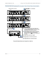
h. Optional: Install an instrumentation cable between the
QUENCH
I/O
connector
~ä
on the rear of the Model 430 Programmer and Aux
I/O connector
~â
=
on the rear panel of the Model 1700 Liquid Level
Instrument. Refer to page 200.
i. Connect each device line cord from the respective device to the
appropriate power receptacle.
j. Remote communications via Ethernet and/or RS-232 can be
accomplished by connecting suitable cabling to the Model 430
Programmer rear panel
ETHERNET
and/or
RS-232
connectors.
k. On the power supply front panel, set the MODE to VOLTAGE (to the
left), and set both the VOLTAGE CONTROL and the CURRENT
CONTROL switches to the OFF position (to the right).
Summary of Contents for 430
Page 2: ......
Page 16: ...XVI REV 9 AMERICAN MAGNETICS INC FOREWORD SAFETY SUMMARY ...
Page 28: ...12 REV 9 AMERICAN MAGNETICS INC INTRODUCTION OPERATING CHARACTERISTICS ...
Page 64: ...48 REV 9 AMERICAN MAGNETICS INC INSTALLATION POWER UP AND TEST PROCEDURE ...
Page 208: ...192 REV 9 AMERICAN MAGNETICS INC SERVICE RETURN AUTHORIZATION ...
Page 248: ...232 REV 9 AMERICAN MAGNETICS INC APPENDIX SHORT SAMPLE MODE ...


