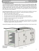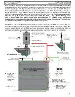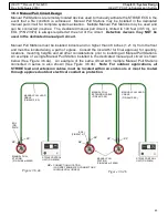
39
HELIX™ Manual
(P/N 26291)
Chapter 3: System Design
Rev A (February 2018)
HELIX™ PCU
Fire Suppression System
When additional circuits are needed, in
addition to the default configuration as shown
in Table 3
.6.1, STRIKE Control Unit
programming is required to enable those
additional circuits (See Section 4.10). A more
complex system design may require the use of
those available circuits for additional protection
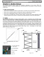
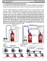
or system requirements. In the figure below,
dual detection and release circuits are utilized
to facilitate Amerex COBRA Kitchen Fire
Suppression along with HELIX PCU Fire
Suppression System installations (Zone #1 &
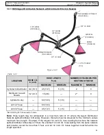
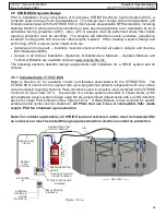
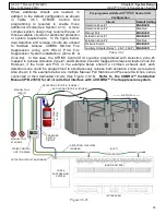
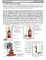
Zone #2). In this case, the STRIKE Control Unit could be programmed with Detection Zone #1
mapped to release Actuation Zone #1 and Detection Zone #2 mapped to release Actuation Zone #2.
However, if the hood and PCU in the example below shared a common exhaust duct, each
detection zone could be programmed to simultaneously release both actuation zones as required.
Also shown in the example below are multiple Manual Pull Stations and Pressure Switches, series
connected in their dedicated circuits (See Figure 3.6.1b).
Refer to the COBRA™ Installation
Manual (P/N 23853) for all circuits that interface with a COBRA™ Fire
Suppression system.
Pre
-
programmed Default
STRIKE
Control Unit
Configuration
Circuit
Default Setting
Detection Zone #1
ENABLED
Detection Zone #2
Disabled
Manual Pull
ENABLED
Actuation Zone #1
ENABLED
Actuation Zone #2
Disabled
Pressure Switch
ENABLED
Auxiliary Outputs (Relay 1, 2 & 3; FACP)
ENABLED
Table 3.6.1
DETECTION CIRCUIT #1 (ZONE #1)
MANUAL PULL
STATIONS
MANUAL PULL
CIRCUIT
STRIKE
CONTROL
UNIT (P/N 23826)
COBRA
SUPPRESSION
SYSTEM
(APPLIANCES)
(HOOD & FILTERS)
ACTUATION CIRCUIT #2 (ZONE #2)
(DUCT)
PRESSURE
SWITCH
CIRCUIT
DETECTION CIRCUIT #2
(ZONE #2)
Figure 3.6.1b
AIR FLOW
ACTUATION CIRCUIT #1 (ZONE #1)
P
C
U
S
U
P
P
R
E
S
S
IO
N
S
Y
S
T
E
M


