58
HELIX™ Manual
(P/N 26291)
Chapter 4: System Installation
Rev A (February 2018)
HELIX™ PCU
Fire Suppression System
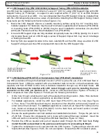
4.7.4 LHD Support Clip (P/N 16501/23524) & Support Tubing (P/N 24539) Installation
An LHD must be supported at a minimum of every 24” (0.61 m) using LHD Support Clips with LHD
Support Tubing (or P
-
Clamps). A support is also required within 3” (0.07 m) of an EOL Module
connected to the end of an LHD. It is recommended that the LHD Support Clips be installed first
with the LHD temporarily placed in a series of clips before installing the LHD Support Tubing. Install
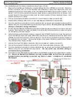
these items per the following instructions (See Figure 4.7.4):
1.
Mount the LHD Support Clips to a suitable mounting surface using the 1/4” mounting hole.
Installer supplied 1/4” fasteners may be used or Amerex supplied Quick Fasteners (P/N 24832)
or mounting rivets (P/N 20535 or 20536) may be used. Installation instructions are provided
with Quick Fasteners and the Rivet Installation Tool (P/N 20552).
2.
Once all LHD Support Clips are fully installed, temporarily route the LHD by placing it in in each
clip location Never pull an LHD through a series of Support Clips which may result in damage
or chafing to the LHD.
3.
Moving from one support location to the next, carefully lift out the LHD, wrap a section of LHD
Support Tubing around the LHD and press both back into the LHD Support Clip.
ROUTE LHD THROUGH ALL
INSTALLED LHD CLIPS.
POSITION AS NEEDED.
AT EACH LHD CLIP LOCATION,
LIFT LHD AND ADD SUPPORT
TUBING (P/N 24539).
Figure 4.7.4
SNAP LHD AND TUBING
INTO LHD CLIP TO LOCK
LHD IN PLACE.
4.
7.5 LHD Quik Seal (P/N 24737) or Compression Seal (P/N 26427) Installation
Any LHD penetration through the bulkhead or wall of a PCU requires the use of an LHD Quik Seal or
Compression Seal. LHDs are supplied with an uninstalled male connector on the downstream side
(opposite end from STRIKE Control Unit) to facilitate installation through any LHD Quik Seals.
All
LHD Quik Seals must be installed with LHD routed through each prior to installing the male
connector on the LHD per Section 4.7.6.
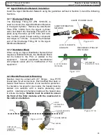
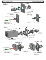
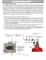
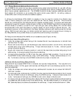
Install an LHD Quik Seal (See Figures 4.7.5a/b/c) or
LHD Compression Seal (See Figures 4.7.5d/e/f) per the following instructions:
1.
Drill a hole through a bulkhead or wall at the selected mounting location. (Note: Hole diameter
depends on indoor or outdoor applications as described below)
2.
For
indoor
applications, install the LHD Quik Seal (P/N 24737) into the hole (See Figure
4.7.5a). Note: The LHD Quik Seal may be oriented in either direction with the body located on
either side of the bulkhead. For
outdoor
applications, install a Quik Seal (P/N 14204) into the
hole, install a Compression Seal (P/N 26427) into the Quik Seal, and install outdoor conduit/
junction box as needed (See Figure 4.7.5d).
3.
Ensure the sealing washer and lock washer are installed where shown. Torque the jam nut to
25
-
30 ft
-
lb. Ensure the compression nut is loose with internal fiber seal installed. Insert the
LHD end (with no connector) through the LHD Quik Seal (See Figure 4.7.5b/e).
4.
Position the LHD as needed and pull all required slack through the LHD Quik Seal.
Fully
install the LHD as described in the previous section prior to proceeding to Step 5.
5.
Tighten the compression nut to seal and lock the LHD in place. Tighten using a wrench until
fully bottomed (See Figure 4.7.5c/f). Do not over
-
tighten. Ensure the LHD is locked in place.

