100
HELIX™
Manual (P/N 26291)
Chapter 6: Recharge
Rev A (February 2018)
HELIX™
PCU Fire Suppression System
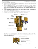
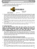
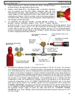
Valve Disassembly (See Figure 6.2.4a):
6.
Unscrew
and remove Downtube from Agent Cylinder Valve using a 1 ½” [38 mm] open end
wrench on hex section of Downtube.
7.
Using a 5/16” [8 mm] open end wrench to hold the Valve Stem Cup on bottom, carefully
remove the Valve Stem (P/N 10095) by unscrewing the Valve Stem Screw (P/N 10732) on top
using a 1/8” [3 mm] hex wrench. Use caution, as the Valve Stem Screw and Washer are spring
loaded.
8.
Inspect and clean the Spring (P/N 10097), Valve Stem Screw (P/N 10732), and Washer (P/N
10102). Replace any damaged components
.
9.
Remove and discard Valve Stem. Replace with a new Valve Stem (P/N 10095).
10.
Clean and rinse entire Agent Cylinder Valve with water and dry all parts.
11.
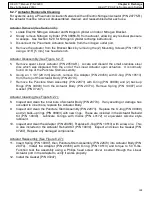
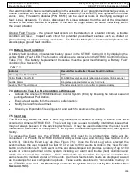
Inspect all external components of the Agent Cylinder Valve including the Pressure Gauge
(P/N 08714), Gauge Guard (P/N 08680), Pressure Switch (P/N 17609), and Rupture Disc (P/N
25646) (See Figure 6.2.4b). If any components are damaged, remove and replace. Seal
threads with a 24 hour epoxy.
Figure 6.2.4b
PRESSURE SWITCH (P/N 17609)
PRESSURE GAUGE (P/N 08714)
(UNDER GUARD)
RUPTURE DISC (P/N 25646)
GAUGE GUARD (P/N 08680)
WASHER
(P/N 10102)
SPRING
(P/N 10097)
VALVE STEM SCREW
(P/N 10732)
Figure 6.2.4a
VALVE STEM
(P/N 10095)
VALVE STEM CUP
DOWNTUBE HEX
PRESSURE SWITCH
(P/N 17609)
AGENT CYLINDER
VALVE
QUAD RING
(P/N 05239)

