38
HELIX™ Manual
(P/N 26291)
Chapter 3: System Design
Rev A (February 2018)
HELIX™ PCU
Fire Suppression System
3.6 STRIKE ECS System Design
Prior to installation of any components of the Amerex STRIKE Electronic Control System (ECS), a
complete system design must be established. This design must comply with all requirements and
limitations associated with the STRIKE ECS in this manual, all applicable NFPA standards, including
National Electric Code and all other standards or laws deemed applicable to an installation by local
authorities having jurisdiction (AHJ). Also, a PCU analysis must be performed where filter banks
requiring protection must be identified. The analysis will determine nozzle quantities, penetration
locations, routing paths and hose and cable lengths required. When creating a system design and
performing a PCU analysis, some helpful tools are:
•
Cameras and note pads – Installers must document and retain all system designs and create a
Bill of Materials (BOM).
•
Access to all Amerex Installation, Operation, & Maintenance Manuals – Updated Manuals and
Technical Bulletins are available
online at www.amerex
The following sections describe design requirements and limitations for a HELIX system and its
circuits.
3.6.1 Introduction to
STRIKE
ECS
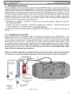
Refer to Section 2.7 for available circuits and features associated with the STRIKE ECS. The
STRIKE ECS Control Unit is supplied with a pre
-
programmed default configuration with only certain
circuits enabled, requiring that only those circuits be used in a system and connected to the STRIKE
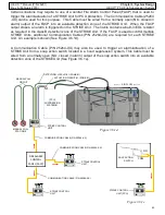
Control Unit (See Table 3.6.1). An example of a simple system schematic is shown below, which
demonstrates a basic system design using the pre
-
programmed default setup with an LHD detection
device for single PCU protection (See Figure 3.6.1a). A Relay Module is also included for electric
external device control and fan shutdown.
All PCUs that use Class A combustible filter media
require PCU fan shutdown upon actuation.
Note: For outdoor applications, all STRIKE lead and extension cables must be located within
an enclosure or must be routed through approved outdoor electrical conduit as protection.
MANUAL
PULL
STATION
RELAY MODULE
(P/N 24695)
A/C POWER
IN
EXTERNAL
DEVICE A/C
POWER
CIRCUITS (2)
LHD
MANUAL PULL
CIRCUIT
SINGLE DETECTION
CIRCUIT (ZONE #1)
SINGLE ACTUATION
CIRCUIT (ZONE #1)
STRIKE CONTROL
UNIT
(P/N 23826)
AIR FLOW
Figure 3.6.1a
PRESSURE SWITCH
CIRCUIT
(PCU)
P
C
U
S
U
P
P
R
E
S
S
IO
N
S
Y
S
T
E
M

