34
HELIX™ Manual
(P/N 26291)
Chapter 3: System Design
Rev A (February 2018)
HELIX™ PCU
Fire Suppression System
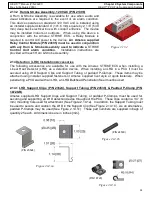
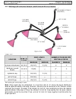
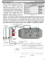
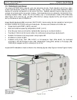
DISTRIBUTOR BLOCK
(P/N 10178
-
R)
1/2” I.D. HOSE
3/4” I.D. HOSE
1/2” ELBOW
(OPTIONAL)
3/4” ELBOW
(OPTIONAL)
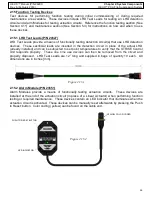
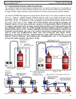
Figure 3.4.3
TO DISCHARGE FITTING KIT
(P/N 10199
-
R)
QUIK SEAL
(P/N 14204)
NOZZLE
(P/N 26330)
1/2” 45° ELBOW
(TYP)
3.4.3 HX50 Agent Distribution Network with Distributor Block (4 Nozzle)
LOCATION
HOSE I.D.
in (mm)
HOSE LENGTH
ft (m)
NUMBER OF ELBOWS PER
SECTION OF HOSE
MAXIMUM
MINIMUM
MAXIMUM
MINIMUM
Cylinder to Distributor
3/4 (19.1)
45 (13.7)
5 (1.5)
2
0
Distributor to each
Nozzle
1/2 (12.7)
15 (4.6)
—
2*
0
Cylinder to any
—
60 (18.3)
5 (1.5)
—
—
All 1/2” hose
—
60 (18.3)
—
—
—
All 3/4” hose
—
45 (13.7)
5 (1.5)
—
—
Table 3.4.3
Note:
Hose length may be unbalanced in a maximum ratio of 3:1 where the Agent Distribution
Network splits (Distributor to Nozzle). However, this ratio must be observed for the minimum versus
maximum hose length. Example: If the longest 1/2 inch I.D. hose leading from where the network
splits (Distributor to Nozzle) is 15 feet, the shortest 1/2 inch I.D. hose leading from the same network
split location cannot be less than 5 feet, and all 1/2 inch I.D. hoses together must fall within the
length specified.
*Not including 45° elbow used at nozzle

