background image

EN

20

Green tab for Settings 

:

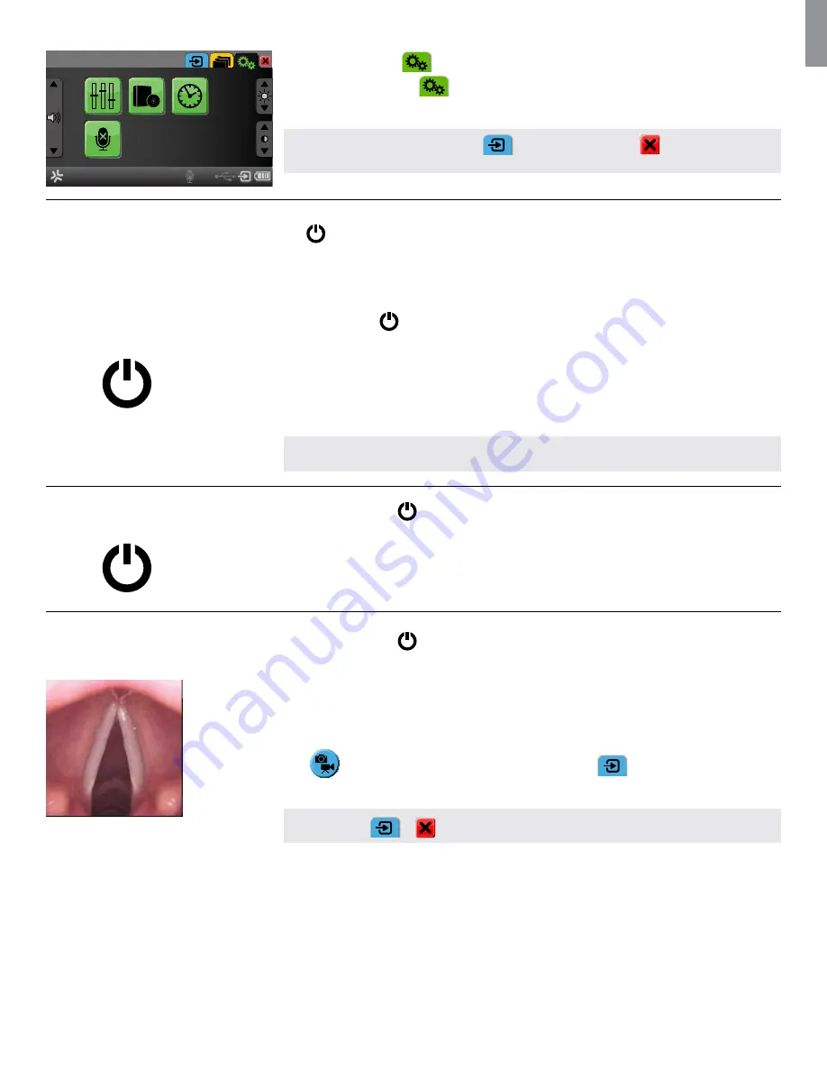
Press the green 

Settings

 tab 


to setup system settings, to administer user accounts and to  

upgrade firmware.
 

NOTE:

  Press the blue 

Live Image

 tab  


or RETURN SIMPLE MODE 

 to view a live image 

from a connected Ambu Visualization Device with just one click.

7.2. How to operate aView

aView only has one physical button located on the top 

 for power ON and OFF.

All other functions are operated using the User Interface controlled from the front touch screen panel.

How to turn ON aView

(Assumption: aView is powered down)


Press power button 

 on top of the aView for at least one second.


- The power button will light up orange for 2 seconds


-  The power button will stay lit and orange if aView is charging or change to green and stay lit green 

if not charging.


- aView is now in STARTUP IMAGE MODE.


-  A live image will appear within 1-2 seconds if a Ambu Visualization Device is connected or a blue 

screen will appear. - After about one minute, aView will be ready in Simple Mode.

NOTE:

  During startup the screen may flicker for about a second. 

How to turn OFF aView

(Assumption: aView is powered ON)


Press the power button


 on top of the aView for at least two seconds.

The light of power button goes off if not charging or stays lit orange if charging.


 A blue hourglass indicating that aView is powering down will appear on the screen and aView will 
power down. 

How to view a live image

(Assumption: aView is powered off and  
the Ambu Visualization Device is connected) 

Press the power button


 on top of the aView for at least one second.

STARTUP IMAGE MODE is initiated showing the live image within 1-2 seconds. The moving icon is shown 
to the right to indicate that User Interface is loading.

SIMPLE MODE is automatically entered when the User Interface is loaded and the User Interface is shown 
to the right of the live image.

Press 

 to enter ADVANCED MODE and the blue 

Live Image

 tab 


will be entered and the live 

image shown.

NOTE:

  Press 


or 

 from anywhere in ADVANCED MODE to see the live image.

Summary of Contents for aScope 3 5.0/2.2

Page 1: ...Instructions for use Ambu aScope 3 5 0 2 2 aScope 3 Slim 3 8 1 2 Ambu aView For use by trained clinicians physicians only For in hospital use...

Page 2: ...Fax 44 0 1480 498 405 www ambu co uk Italy Ambu S R L Via Paracelso 18 Centro Direzionale Colleoni 20864 Agrate Brianza MB Italia Tel 39 039 657811 Fax 39 039 6898177 www ambu it Spain Firma Ambu S L...

Page 3: ...ati tmutat 308 335 Italiano Manuale d uso 336 363 364 391 Lietuvi kai Naudojimo instrukcijos 392 418 Latviski Lieto anas instrukcija 419 446 Nederlands Gebruiksaanwijzing 447 474 Norsk Brukerveilednin...

Page 4: ...stem Usage 11 4 Cleaning and Disinfection of aView 15 5 Technical Product Specifications 15 6 Connecting accessories 19 7 How to Operate aView 21 8 Trouble Shooting 32 Appendix 1 Electromagnetic Compa...

Page 5: ...is a single use device designed for use in adults and children It has been clinically evaluated for the following minimum endotracheal tubes ETT and double lumen tubes DLT sizes Minimum ETT inner dia...

Page 6: ...Be careful not to damage the insertion cord or distal tip when using sharp devices such as needles in combination with the aScope 3 Be careful when handling the distal tip of the insertion cord and do...

Page 7: ...connection Unless specified otherwise the text relates to both products In this document the term aScope 3 always refers to both variants If one of the variants is referred to specifically the terms...

Page 8: ...on the bracket Bracket Secures the monitor to e g an IV pole Pouch hook Slide the hook through the 3 holes on the bracket It can now be used to hold the aScope 3 pouch hole in top corner for easy stor...

Page 9: ...tion between 80 and 109 kPa in operating environment Connection to external monitor Direct current Alternating current Symbol of Class II equipment IP30 Protection against solid objects Waste Bin symb...

Page 10: ...EN 10 Lot Number Batch Code Serial Number Warning Consult Instruction for use Year of Manufacture followed by YYYY...

Page 11: ...a charger be readily available during use Place or hang the aView display on a stable support while in use Dropping aView could damage it Position the power cord where it is unlikely to be stepped on...

Page 12: ...awing the aScope 3 If needed remove secretion or blood from the airway before and during the procedure The suction function of any appropriate suction device can be used for this purpose The temperatu...

Page 13: ...nnector is connected to a suction device Apply a vacuum of 85 kPa 638 mmHg or less when suctioning Applying too large a vacuum may make it difficult to terminate suctioning CAUTION Secure the tubing p...

Page 14: ...r use and must be disposed of in accordance with local guidelines for collection of infected medical devices with electronic components Do not soak rinse or sterilize this device as these procedures m...

Page 15: ...View must be submitted to the pre check procedure in section 5 1 Between procedures aView must be stored in accordance with local guidelines 5 Technical Product Specifications 5 1 aScope 3 Specificati...

Page 16: ...D Brightness control Yes Contrast control Yes Start up time About 1 second Memory Storage capacity 8GB Electrical power Power requirement 18V 1 67A DC input Battery type 11 1V 3760mAh Operating enviro...

Page 17: ...shall be discarded aView can be placed on a solid flat surface by using the stand on the back of aView If needed aView can be placed by using the supplied bracket 6 1 Charging aView Connect the aView...

Page 18: ...LE MODE SIMPLE MODE Live image available and the User Interface displays basic user functions Advanced functions can be initiated from SIMPLE MODE by pressing ADVANCED MODE button aView loads the User...

Page 19: ...recorded image NOTE When de selecting a live image by leaving the blue Live Image tab to go to an other tab in ADVANCED MODE aView asks for confirmation Live image vs recorded image in ADVANCED MODE W...

Page 20: ...or a blue screen will appear After about one minute aView will be ready in Simple Mode NOTE During startup the screen may flicker for about a second How to turn off aView Assumption aView is powered...

Page 21: ...lour of the device interface where the Ambu Visualization Device is connected How to take a SNAPSHOT Accessible in ADVANCED MODE blue Live Image tab Keep the Ambu Visualization device as still as poss...

Page 22: ...tion Snapshot has already been located Press the snapshot to select Press to view the snapshot Press or to toggle between snapshots in the folder NOTE Double click to Select and View How to view a vid...

Page 23: ...les are not deleted from aView in the copy process How to set the time and date Accessible in ADVANCED MODE Green Settings tab Press to access system time and date Press to toggle between 12 and 24 ho...

Page 24: ...e ADMIN account is logged in Connect the power adapter before commencing a software update Press to enter software settings Insert USB stick containing the upgrade file in its root directory Press to...

Page 25: ...ED MODE Green Settings tab Press to enter Display settings Press the up or down arrow to adjust the colour for the Red Green and blue The arrow will light up red when pressed and the achieved level wi...

Page 26: ...A communication error has occurred between aScope 3 and aView Restart the system by pressing the ON OFF button on aView for at least 2 seconds When aView is OFF restart by pressing ON OFF button once...

Page 27: ...channel Remove endoscopic accessory Difficult to insert endoscopic accessory through the channel Cause Action Channel blocked Clean the working channel using a cleaning brush or flush the working cha...

Page 28: ...issions IEC EN 61000 3 2 N A N A Voltage Fluctuations Flicker emissions IEC EN 61000 3 3 Complies Guidance and Manufacturer s Declaration Electromagnetic Immunity The aScope 3 system is intended for u...

Page 29: ...tional measures may be necessary such as reorienting or relocating the aScope 3 system unit b Over the frequency range 150kHz to 80MHz field strengths shall be less than 3V m Recommended Separation Di...

Page 30: ...lateral standard Electromagnetic compatibility Requirements for test The Ambu aView power supply conforms with Council Directive 93 42 EEC concerning Medical Devices IEC 60601 1 Medical electrical equ...

Reviews: