CHAPTER 2: GETTING STARTED
SERIES 300 FAST RESPONSE WELD HEAD SYSTEM
990-115
2-11
WARNING:
Always wear safety glasses when welding.
1 At the Power Supply, set the WELD/NO WELD
switch to WELD to go to the run state. Note that
the NO WELD legend on the Power Supply
graphical RUN screen is replaced by the weld time.
2 At the Weld Head Control, press [CHNG] twice to
access the Weld Head Control graphical setdown
RUN screen.
3
Make a test weld by placing the weld pieces on the
lower electrode and pressing on the Weld Head
foot switch. The first level press of the foot switch
will send the upper electrodes to the SRCH
position that you programmed, 0.020 inch above
the workpieces. The second level pressing of the
foot switch will send the upper electrode to the
weld piece surface and trigger the weld cycle.
4 If a partial weld has taken place, peel the welded
materials apart. A satisfactory weld will show
residual material pulled from one material to the
other. The default WELD time of 1ms and the
default CURRENT of 0.5kA, as shown on the
Power Supply graphical RUN screen, will probably
not be sufficient to make a good weld, or any weld.
Also, weld force will need to be adjusted at the
Weld Head Control.
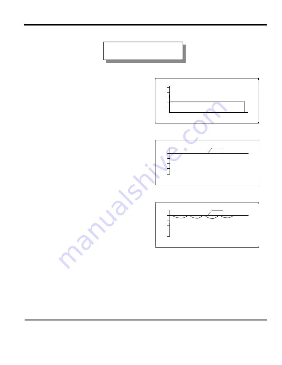
NOTE:
When insufficient weld energy is supplied, oscillations just below the .000 setdown line are typical
for round-to-round or round-to-flat welding applications. When sufficient weld energy is applied, a
negative (downward) swing of the setdown trace is typical.
The first test weld:
default settings
CURRENT SCH: 000 BASIC WELD
1.0
0.8
0.6
0.4
0.2
0.0
▲▼
Select Schedule 1 ms
SCH: 000 SETDOWN: .0000inch WELD: 20.0ms
.000
.001
.002
.003
.004
▲▼
Select Schedule
RUN
SCH: 000 SETDOWN: .0000inch WELD: 20.0ms
.000
.001
.002
.003
.004
▲▼
Select Schedule
RUN
Summary of Contents for 300 Series
Page 1: ...990 115 REV Q ELECTRONIC WELD HEAD CONTROL 300 Series OPERATION MANUAL ...
Page 8: ...SERIES 300 FAST RESPONSE WELD HEAD SYSTEM viii 990 115 ...
Page 32: ......
Page 62: ......
Page 78: ......


