MAX4000 Server and Vision Board
Telephony Hardware Manual 59
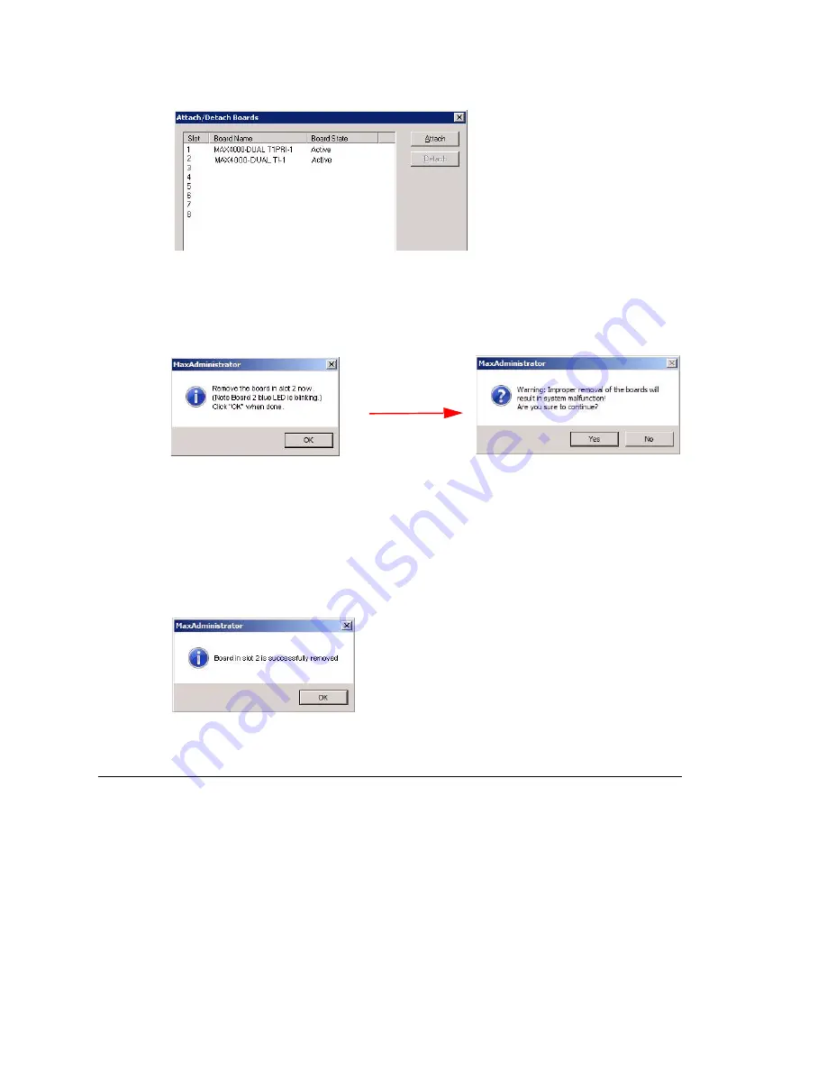
3. Select the board you want to remove. (The bottom slot in the
chassis
corresponds
to “1” in the dialog box, and so forth up to the top slot, which corresponds to “8” in
the dialog box.) When you select a board, the
Detach
button becomes available.
4. Click the
Detach
button. Suppose you chose slot 2. A dialog box like the following
appears:
5. The port LED status lights go out, and the blue light begins to blink. The board, trunk
channel and resource disappear from the MaxAdmin window.
Remove the board: first push in the gray release buttons on both side-swing extrac-
tor handles. (The blue light goes out and the red light comes on when you press in
the gray lever on the right.) Using your thumbs, push the extractor handles to the
side (outwards from center) and back to release the board. Then grab the handles,
and pull the board toward you and out.
6. A message pops up to tell you the board detached successfully:
7. Click
OK
in the confirmation message in MaxAdmin.
Swapping a Power Supply
The MAX4000’s three power supplies, located in the back of the unit, are easily
accessible and hot-swappable (removing or adding a power supply without shutting
down the system or MAXCS does not interfere with the operation of the system). Each
power supply has its own power cord.
BT Question: When
does the dialog on
the right appear?
Summary of Contents for MAX1000
Page 1: ...Telephony Hardware Manual 12 2009 4413 0001 6 5 Update1 ...
Page 6: ...2 Telephony Hardware Manual ...
Page 14: ...FCC Requirements 10 Telephony Hardware Manual ...
Page 30: ...UL Hardware Preparation 26 Telephony Hardware Manual ...
Page 56: ...MAX2000 System 52 Telephony Hardware Manual ...
Page 66: ...Installing and Removing an Access Board 62 Telephony Hardware Manual ...


