Installing and Removing an Access Board
58
Telephony Hardware Manual
5. Insert the board into the slot you chose (in the chassis, you are working from the
bottom up), being careful to align the bottom of the board with the card guides in
the bottom of the slot. The extractor handles on the board should be in the unlocked,
or open, position (pointing outwards). Push the board all the way in until the
extractor handle grooves capture the side beams of the slot, and use your thumbs
to push the extractor handles in toward the center to lock the board into place.
Note:
When the board is correctly plugged in, the blue light in the faceplate begins
to blink, and the red light is off.
6. Click
OK
in the dialog box. The system will show
Active
in the Board State column
for the board, and the blue light in the faceplate will be solid on.
7. Connect the T1/E1/PRI cable(s) to the RJ48c digital ports. The green lights of the
connected T1/E1/PRI ports should be on, and the red lights should stop flashing
within 30 seconds.
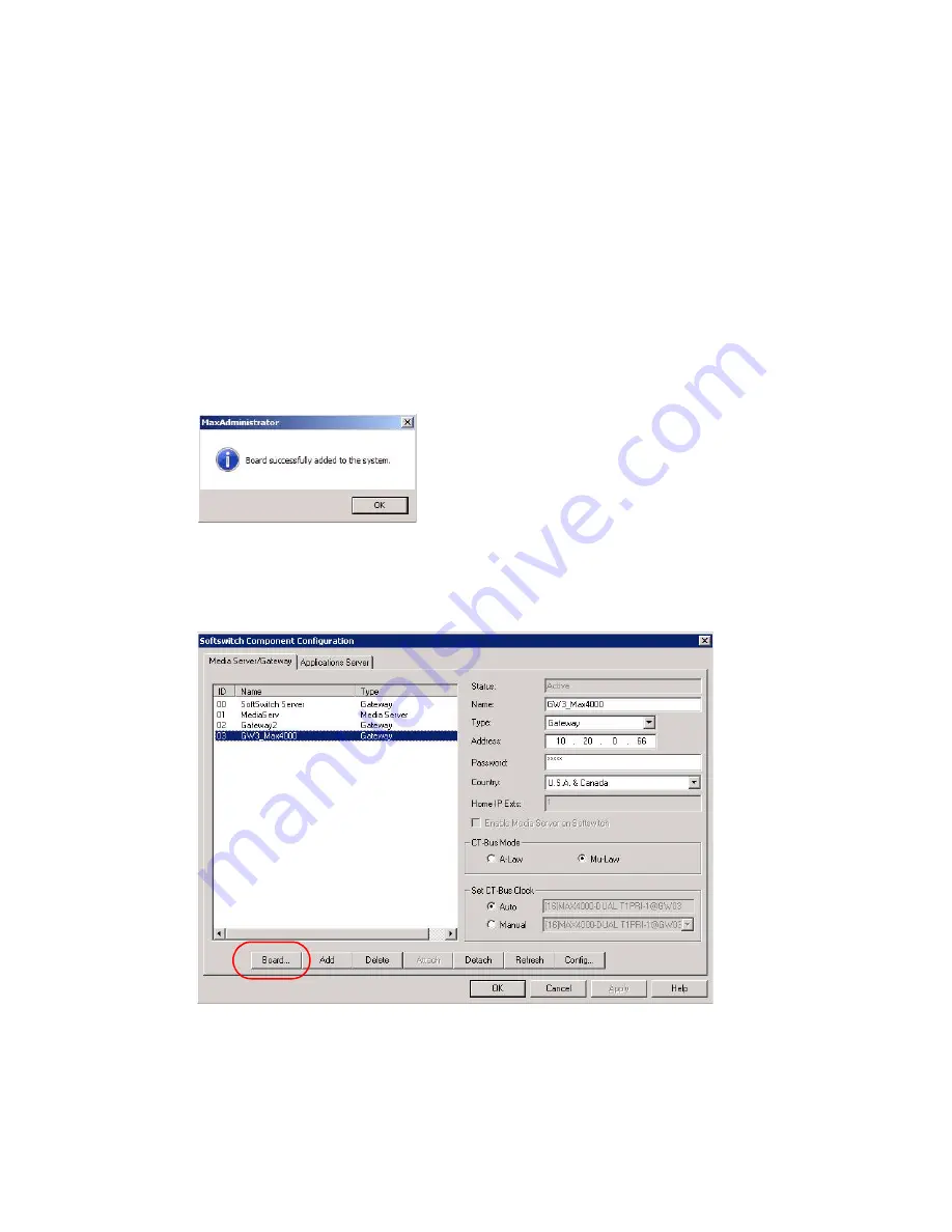
8. The board, trunk channel and resource appear in MaxAdmin, and the board is up and
ready. A message pops up to tell you the board attached successfully:
9. Click
OK
.
Removing a Board
1. In MaxAdmin, go to
System > Softswitch Component Management
.
2. Select MAX4000 and click the
Board
button.
Summary of Contents for MAX1000
Page 1: ...Telephony Hardware Manual 12 2009 4413 0001 6 5 Update1 ...
Page 6: ...2 Telephony Hardware Manual ...
Page 14: ...FCC Requirements 10 Telephony Hardware Manual ...
Page 30: ...UL Hardware Preparation 26 Telephony Hardware Manual ...
Page 56: ...MAX2000 System 52 Telephony Hardware Manual ...
Page 66: ...Installing and Removing an Access Board 62 Telephony Hardware Manual ...


