background image

Page 12

DD8

plus Version 2.20 - September 1998

INTRODUCTION - 1

POWERING UP THE DD8

It is recommended that the following power up procedure is observed when turning the system
on:

First, turn on any disk drives that may be connected to the system. Next, turn on the DD8. You
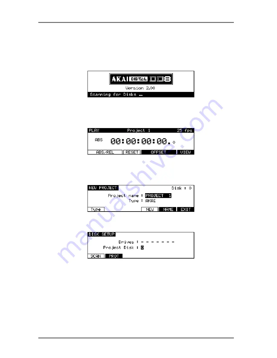
will see this screen display momentarily:

The DD8 will look at the disk drives attached to the system. If a disk containing a valid PROJECT
is found, it will be loaded automatically and you will see the main playback screen:

If no projects are found, the DD8 will enter the NEW PROJECT page in DISK mode, which will
be explained later in Disk mode, to allow you to setup the disks attached to the system and
create a new PROJECT:

If no disk is found, it goes directly to the DISK SETUP page in DISK mode:

In this case, check the connections to the disk drive (and SCSI termination) and then press
the SCAN key to search the SCSI bus again.

Summary of Contents for DD8 Plus

Page 1: ...DIGITAL DUBBER Operator s Manual WARNING To prevent fire or shock hazard do not expose this appliance to rain or moisture...

Page 2: ...tended to alert the user to the presence of important operating and maintenance servicing instructions in the literature accompanying the appliance The lightning flash with arrowhead symbol within an...

Page 3: ...that the unit is well ventilated and away from direct sunlight To avoid damage to internal circuitry as well as the external finish keep the DD8plus away from sources of direct heat stoves radiators...

Page 4: ...SIBLE SHOCK HAZARD SHOULD IT BE INSERTED INTO A 13 AMP SOCKET ELSEWHERE The wires in this mains lead are coloured in accordance with the following code GREEN and YELLOW EARTH BLUE NEUTRAL BROWN LIVE A...

Page 5: ...sant les limites applicables aux appareils num riques de la Class A prescrites dans le R glement sur le brouillage radio lectrique dict par le minist re des Communications du Canada WARNING VENTILATIO...

Page 6: ...al shall not be liable for any injury loss or damage direct or consequential arising out of use or inability to use the product The warranty provides only those benefits specified and does not cover d...

Page 7: ...PANEL 10 OPTION SLOTS 10 AKAINET CONNECTOR 10 TERMINATOR SWITCHES 10 SYNC CONNECTOR 10 EXPANSION CONNECTOR 10 SCSI B ID SWITCHES 10 SCSI A CONNECTOR 10 GROUND TERMINAL 10 MAINS INPUT 10 PRE READ LEVEL...

Page 8: ...RE 41 RESTORING THE ENTIRE BACKUP 45 NOTES ABOUT BACKUP RESTORE 46 SUGGESTIONS FOR BACKUP RESTORE 47 TAKING CARE OF YOUR TAPE DRIVE 48 COPYING DISKS 49 MACINTOSH DISK COMPATIBILITY 51 PROTOOLS IMPORT...

Page 9: ...ACK FUNCTION IN RS422 MASTER 89 USING THE LAYBACK FUNCTION 90 RS422 MASTER CONTROL OF NON LINEAR VIDEO RECORDERS 90 RS422 SLAVE FUNCTIONS 91 RS422 SLAVE EAVESDROPPING MODE 91 RS422 SLAVE FULL SLAVE MO...

Page 10: ...boards 104 PRE READ OUTPUT 104 ANALOG INPUT OUTPUT CONNECTIONS 104 AES EBU INPUT OUTPUT CONNECTIONS 105 RS422 9 PIN CONNECTION 106 BI PHASE INPUT 106 BI PHASE OUTPUT 106 PARALLEL GPIO CONNECTIONS 107...

Page 11: ...udio recording at sample rates up to 96kHz SPECIFICATIONS General Digital audio format 16 bit 20 bit and 24 bit linear PCM Simultaneous recording 8 tracks max Recording time 225 track minutes equivale...

Page 12: ...t imp 94 Max output level 24dBu 25 pin D sub TASCAM DA 88 pin assignment D A converter 20 bit 8 times oversampling Operating level selectable by software 12 16 18 or 20dBu IB D8TIF 8 channel TDIF digi...

Page 13: ...or Multi AES EBU interface Standard accessory Cable set for AD DA boards and SCSI Drive connection 1 Power cable 1 Operator s manual 1 0dBu 0 775Vrms Trademarks Open Media Framework and OMF are tradem...

Page 14: ...llowing synchronisation to house sync digital audio and PAL SECAM and NTSC video sync sources 20 bit digital to analogue converters DACs with 8 x oversampling and software adjust able operating level...

Page 15: ...t of some of the terms you will come across during the course of this manual PROJECT This is where you do the bulk of your work on the DD8 and con tains all your recordings positioned at the required...

Page 16: ...long the DD8 will stop playing Under the power switch the PANEL ENABLE DISABLED switch is used to lock the keys on the front panel to prevent accidental operation The PLAY RECORD NUDGE and TRACK SLIP...

Page 17: ...essed during play the DD8 will fast forward with tape chatter just like a standard MTR In this case only x 5 play speed is possible This is rewind Pressing it once gives x 10 play speed pressing it ag...

Page 18: ...ou change your mind The ES CAPE key can also be used to take you out of the current page and back to the main play record mode The UNDO key allows you to undo redo the last thing you did If you make a...

Page 19: ...DISK EJECT button Power must be on for the disk to be ejected as the mechanism is motorised NOTE If there is some problem ejecting the disk and or power is not applied to the drive you can eject the...

Page 20: ...ds IB D8AD 8 channel analog input and IB D8DA 8 channel analog output AKAINET CONNECTOR This connector is used to connect the DD8 to the DL1500 Remote Controller TERMINATOR SWITCHES These switch selec...

Page 21: ...e the pre read output generated by some dubbers that have a second playback head mounted before the main playback head Note that the DD8 does not generate an audio signal here Instead it uses an oscil...

Page 22: ...tached to the system If a disk containing a valid PROJECT is found it will be loaded automatically and you will see the main playback screen If no projects are found the DD8 will enter the NEW PROJECT...

Page 23: ...le shown above the timecode display style has been set to display footage However it is also possible to select conventional timecode formats in which case the display will look something like this Th...

Page 24: ...Using the soft keys on this page you may set offsets so that the two machines play in sync without having to extensively modify the project s start time Pressing the ABS REL F1 F2 key sets the time d...

Page 25: ...f 09 00 00 00 0 adding 9 hours to the incoming timecode so that it plays from 10 hours In cases where the project and the incoming timecode both start at odd times for example when the project starts...

Page 26: ...g TYPE F3 takes you to the RECORD TYPE page where you can select certain options for new recordings The TYPE key F1 is used to move the cursor to the FILE TYPE field The BITS key F2 is used to move th...

Page 27: ...4 BIT 20 BIT 20 BIT PACKED Note that this mode does not involve any audio compression It just places the data on disk in an optimal manner to maximum disk storage space and bandwith Once you have sele...

Page 28: ...ing prompt will appear when you try to start recording UNDOING A RECORDING If you don t like the recording you just made the simplest way to repair it is probably to record over it just like tape Anot...

Page 29: ...y to manually put the DD8 back into record to transfer the audio in the example above The Record Rushes function overcomes this and allows continuous recording on the DD8 despite breaks in the source...

Page 30: ...de has been entered When enter ing the Nudge mode the displayed amount is always zero The final amount is committed when exiting the NUDGE mode Pressing SELECT CUE F3 F4 selects all of the cues at the...

Page 31: ...ip amount of a track is different from zero the according TRK SLIP LED under the Meters will be steadily lit even when returning to another mode This condition can be thought of as a Track slip previe...

Page 32: ...film picture usually a cross before the first frame STORE Pressing the STORE key will show the following screen Pressing IN F1 stores the current NOW time as the IN point Pressing OUT F2 stores the cu...

Page 33: ...enter the numbers The important thing to remember is to confirm the time division using the numeric keypad s 00 double zero key If you wish to enter a timecode value with a sub frame use the procedure...

Page 34: ...formatted project disk containing one or more projects is selected pressing the SE LECT key F5 F6 will take you to the LOAD PROJECT page If the disk is formatted but does not contain any projects pres...

Page 35: ...F1 and F2 keys to move the cursor to the left right Use the DATA keys to scroll through the available characters in order to set the name for the new project When you are finished press ENTER to set t...

Page 36: ...nd copy Pressing NEW F5 goes to the NEW PROJECT page where you can create a new project Pressing LOAD F6 loads the Project currently selected by the highlighted cursor After a project is loaded the DD...

Page 37: ...ish to view Pressing DELETE F5 deletes the Project selected by the cursor UTILITIES PAGE Pressing UTILITIES on the LOAD PROJECT page will take you to the following screen Here you may perform certain...

Page 38: ...that this option will create a single volume erasing all existing partitions on the disk If you want to create multiple partitions it will be necessary to use a third party Macintosh disk formatting a...

Page 39: ...sk after which if FORMAT CERTIFY is selected as the format operation it goes through the disk searching for bad blocks and marking them so that they won t be used We recommend that you do a full forma...

Page 40: ...Format Is Read Only EXTENDED format disks can be easily updated to DD PLUS format as described in the next section UPDATING EXTENDED FORMAT DISKS When an EXTENDED format disk is selected on the DISK...

Page 41: ...ee no change or only a small change in the FREE ON DISK field because unlike MINIMISE if just one cue in one project uses one second of a ten minute recording the whole ten minutes will be kept If you...

Page 42: ...ere is no good reason why you should have your project on one removable disk and all the audio associated with it on another and it is a practice that should be avoided Presumably the reason a removab...

Page 43: ...scribed above because it is possible for projects and audio to exist on separate disks if a project disk is missing from the system you may cause data to be lost if a disk is missing from the system P...

Page 44: ...up to SCSI tapes When you press the BACKUP key F3 you will be taken to this screen Before we look at the actual functions an understanding of SCSI tape drives is in order SCSI tape drives can be regar...

Page 45: ...ms to be taking a long time you can press ESCAPE to abort the formatting process To avoid this it is recommended you always use new unused tapes It is also not a good idea to use tapes that may have b...

Page 46: ...SCSI tape You may select SELECTED FILES You may via F5 SELECT select specific files to backup ALL PROJECTS You may backup all the projects on the selected disk ALL LIBRARIES You may backup all the lib...

Page 47: ...As well as selectively backing up chosen files or backing up all projects and or libraries you may also make a duplication of the disk by selecting ENTIRE DISK in the BACKUP TYPE field NOTE Although...

Page 48: ...ghlighting bar The percentage in the top line shows how much of the individual file has been backed up whilst the percentage in the bottom line shows how much of the entire backup has been done If any...

Page 49: ...as the two media should have identical contents If however you make a new recording on the source disk or delete any thing from the source disk after the backup the contents of both media will not be...

Page 50: ...F5 6 You will see this screen As you can see this is basically the reverse of the SCSI BACKUP page The fields are TITLE Shows the name of the backup you wish to restore RESTORE TYPE Selects what will...

Page 51: ...e you see a list of all the backups on the tape and the number of files cues clips contained within them In this case there are just three backups If more than five backups exist on the tape up down a...

Page 52: ...is screen The DD8 needs to read the directory on the tape to know what files are contained in it Press YES F5 to proceed or F6 NO to cancel You will see this screen Depending on the complexity of the...

Page 53: ...across the bottom of the LCD to further indicate progress You will then see this display What the DD8 is doing here is fixing up all references to the audio data that has just been restored so that a...

Page 54: ...cally numbered name Using the above example pressing NO at the OVERWRITE prompt would create a new library called ANIMALS 1 or some other suitably numbered library of that name Pressing YES F5 6 will...

Page 55: ...of restore except that when you press ENTER you are prompted thus You have the option to completely wipe the selected disk prior to restoring data back onto it Respond by pressing NO or YES as appropr...

Page 56: ...to tape but these will be restored to the disk selected in the RESTORE TO field in this ex ample Disk ID 0 In other words you should ensure that the destination disk for the restore is large enough to...

Page 57: ...e media is small doesn t mean it doesn t deserve the same respect as a hefty 10 reel of master tape Naturally keep backup tapes away from magnetic sources such as monitor speakers etc If you have to s...

Page 58: ...Don t smoke near the tape drive This can really clog the heads Do not try to use the tape drive if you move it from environments of differing temperatures and humidity Moisture on the head as a result...

Page 59: ...l copy all the libraries on the source disk to the destinations disk DUPLICATE DISK This will copy everything from the source disk to the destination disk IMPORTANT NOTE DUPLICATE WILL FIRST ERASE THE...

Page 60: ...eferencing the full 5 minutes of audio but only playing the relevant 30 seconds of it in the project When you copy the project across it will only copy the 30 second section you are using in the proje...

Page 61: ...elected disk This may be used to select any OMF files that are not recognised by the DD8 This may occur if the OMF file was created on a non Macintosh system NOTE Due to the limited screen size the DD...

Page 62: ...l load and playback all fade regions from the rendered fade files on disk If you have created any custom fades in Protools you should choose this option to ensure the DD8 plays back the file correctly...

Page 63: ...gener ated Note that the PRE READ function is driven from the envelope files so it will not function with projects imported from OMF files Some OMF files contain pre computed rendered fades If these...

Page 64: ...e you to the IMPORT TRACKS page which can be used to select the 8 tracks that will be imported Soft keys F1 F2 and F3 can be used to quickly select tracks 1 8 9 16 or 17 24 Alternatively you can selec...

Page 65: ...file type field where you can select the type of file you want to load Normally this should be left on PROJECT to view the available projects on the disk ALL FILES can also be selected to view a list...

Page 66: ...ight MFX3 plus also allows a separate MDL Media Description Language file to be created which contains all the information to play the audio in the current project This is identified with a DL suffix...

Page 67: ...e SAVE PROJECT page The project to be exported will be the one that is currently loaded into memory Pressing DISK F1 will move the cursor to the TO DISK field where you can select the SCSI ID of the d...

Page 68: ...e project If the Handle is very large it is likely that the source audio files will be copied intact without being minimised DD1000 DISK COMPATIBILITY The DD8 uses the same disk format as the Akai DD1...

Page 69: ...d up After saving a project to a DD1000 disk from the DD8 the next time this disk is used you can choose to load the DD8 project rather than the DD1000 Qlist by pressing the SELECT key F5 F6 on the DI...

Page 70: ...g illustrates the difference between the two methods A cue in a DD1000 Qlist says Play TAKE N from the disk in the drive with the SCSI ID X If it can find that take on the disk in the drive with ID X...

Page 71: ...ou must edit each cue separately in the DD1000 If the DD1000 Qlist s audio comes from more than one disk then the original situation remains and the disks must be placed in the correct drive in order...

Page 72: ...want to save your changes press DON T SAVE F5 F6 You can always save your settings later by going back to the SYSTEM pages and pressing the SAVE soft key If you want to save the settings to disk with...

Page 73: ...ning This is the selection used when using the DD8 on its own when using it with external video equip ment to prevent drift of audio to picture it is recommended to sync the entire system i e VTR DD8...

Page 74: ...will play back at the wrong speed For example if the wordclock being received is 44 1kHz and you try to play back a recording made at 48kHz the recording will play back slow Please make sure that you...

Page 75: ...pecial dual channel mode where inputs and outputs are paired INPUTS OUTPUTS 1 2 3 4 5 6 7 8 1 2 3 4 5 6 7 8 IN 1 IN 2 IN 3 IN 4 OUT 1 OUT 2 OUT 3 OUT 4 This is similar to the high sample rate support...

Page 76: ...hronise to timecode running at 25 frames per second This would normally be selected when sync ing to EBU timecode in Europe SMPTE 29 97 nd This selects that the DD8 will synchronise to non drop timeco...

Page 77: ...used when working with material that has been trans ferred from film in this way Whilst working with the video the audio will play back slightly faster and may sound unnatural but this is not a probl...

Page 78: ...ate The options are NONE This will stop the DD8 generating timecode SMPTE EBU selection These will generate timecode at the selected frame rate NOTE The DD8 cannot generate and receive LTC at the same...

Page 79: ...screen will change to allow you to enter the required offset time Soft keys F1 and F2 can be used to move the cursor to the sub frame field or any of the other fields The offset time is then entered...

Page 80: ...age to the equipment or to the film or tape Pressing Max F1 moves the cursor to this field TIME TO MAX SPEED This allows you to set how long it will take for the connected equip ment to reach its maxi...

Page 81: ...annoying bursts of audio from random access machines The options for the REVERSE CHASE field are UNMUTED The DD8 will attempt to play audio while chasing reverse timecode MUTED The DD8 will mute play...

Page 82: ...cond 29 97 fps drop drop frame 29 97 frames per second 30 fps non drop 30 frames per second 30 fps drop drop frame 30 frames per second Feet 24fps 16mm feet and frames at 24 frames per second as refer...

Page 83: ...LCD Contrast field This allows the contrast of the LCD display to be changed for better visibility by using the DATA keys DISPLAY OFFSET Pressing OFFSET F5 takes you to the DISPLAY OFFSET page When t...

Page 84: ...l hear the input signal under the following conditions HEAR INPUT RECORD STOP PLAYBACK YES NO YES RECORD TRACK S PLAY SELECT KEY ON RECORD STOP PLAYBACK YES YES RECORD TRACK S PLAY SELECT KEY OFF YES...

Page 85: ...Also when recording four tracks there may be gap in monitoring when you drop out of record The actual recording will be fine only the monitoring at the point of punch out will be momentarily affected...

Page 86: ...cue will not cause the original cue s to be deleted from disk For example DROP IN DROP OUT DROP IN DROP OUT DROP IN DROP OUT DROP IN DROP OUT DROP IN DROP OUT Will not erase original recording Will no...

Page 87: ...MODE IS USED After you have just loaded a new project as a safety factor recording over cues in that project will not delete their audio from disk and the original project cannot be damaged If howeve...

Page 88: ...ged while the transport is in record Available selections are NORMAL This is the default setting The record track selection can not be changed while the transport is in record TRACK KEYS In this mode...

Page 89: ...ssignment Inputs 1 8 to tracks 1 8 Other Input assignments are made by pressing the Track Key 1 8 to select a track and then using the DATA keys to select the required input SPEED Pressing SPEED F5 on...

Page 90: ...es the cursor to the Pre Read On OFF field This enables the Pre Read function and causes the DD8 to load pre read data into memory NOTE The Pre Read function requires an area of memory to store inform...

Page 91: ...of audio after the NOW time that will be played when the FROM key is pressed JOG Pressing JOG F5 on the second System Settings page takes you to the Jog menu Pressing Jg Res F1 move the cursor to the...

Page 92: ...the AKNET key takes you to a page which shows the Ethernet ID number assigned to the machine This number is programmed during production The other parameters on this page are described later in the s...

Page 93: ...on the left hand side of the RC15 SETUP screen The 8 transport keys are listed as F1 F8 and the transport keys are listed as TRANSPORT 1 TRANS PORT6 The DATA keys are used to select the function for e...

Page 94: ...rab MARK time SYNC ON LINE Switch EXT TIME on off REHEARSE Switch REHEARSE on off AUTO PUNCH Switch AUTO PUNCH on off REC TRACK 1 8 Switch selected record track on off BPH RCV RESYNC Resync biphase re...

Page 95: ...ing the track keys 1 8 to select a playback track and using the DATA keys to select the required source After changing the mapping for individual tracks a new soft key SET MAPPING will appear Press th...

Page 96: ...r settings REAL TIME CLOCK Pressing CLOCK F5 on the third System Settings page takes you to the SYSTEM CLOCK SETUP page To change the current time press HOURS F1 MINS F2 or SECS F3 to move the cursor...

Page 97: ...AINET Termination NOTE The AKNET interface used in the DD system is 10 Base 2 Ethernet There are cer tain rules that must be adhered to when setting up the system to ensure reliable operation All cabl...

Page 98: ...MPTE input T C out House Sync Source RS422 equipped VTR DD8 with RS422 and LTC option boards RS422 SETUP PAGE Pressing the SYSTEM key followed by REMOTE and RS422 takes you to the RS422 SETUP page whe...

Page 99: ...you can place the sound effect nudging it backwards or forwards in sub frame increments on the DD8 until you think it s at the right position You can then re engage the VTR by switching on the SYNC ke...

Page 100: ...the end of the project and press LAYBACK F3 F4 to transfer the whole project back to the master video tape in one pass Another use of this may be to receive a video tape as described above but the swe...

Page 101: ...ou choose largely depends on your setup RS422 SLAVE EAVESDROPPING MODE In the RS422 SETUP page SYSTEM REMOTE RS422 select EAVESDROP SLAVE in the RS422 MODE field You will see this screen You will see...

Page 102: ...ntrollers offer selection of the VTR s digital audio tracks which are selected on the video edit controller itself by way of keys labelled D1 n where n is the highest number track available on the vid...

Page 103: ...tracks keys on a MAG machine when a record track is selected the transport will immediately drop into record When the transport motion stops all record track selections are automati cally cleared MULT...

Page 104: ...6 Record Track 6 Tally GPO 7 Record Track 7 Tally GPO 8 Record Track 8 Tally GPO 9 Record Tally GPO 10 Play Tally GPO 11 Rehearsal Tally GPO 12 Mag Multitrack Tally You can change these assignments b...

Page 105: ...activated it will mark an OUT point RESET BIPHASE This will reset the biphase receiver TOGGLE EXT TIME When activated it will switch on off the external time source RECORD REHEARSE This will switch o...

Page 106: ...The applications for these inputs are enormous You may as mentioned build a simple play only remote You may use the GPOs of another machine to remotely control the DD8 for example a dialogue recordin...

Page 107: ...vel when RECORD is activated EXT TIMECODE OK The GPO will change level while external timecode is being successfully received EXT WORDCLOCK OK The GPO will change level while external wordclock is bei...

Page 108: ...le disk Furthermore different drives SCSI implementation can vary quite dramatically In our tests a drive with an access speed of around 10 milliseconds and a transfer rate of around 3Megabytes per se...

Page 109: ...s put on line Note that there is no restriction into which drive a removable disk can be placed If on System A the music disk was on Drive ID 0 the sound effects on Drive ID 1 the foley on Drive ID 2...

Page 110: ...IB 805R RS422 Interface Board IB 806B Biphase Interface Board and IB 808G GPI O Interface Board The options installed from underneath include the EDO SIMMs memory board not made by AKAI for buffer RAM...

Page 111: ...installed at the same time use the second connector instead of the first one of the 60 pin AD DA cable The same 60 pin cable is used for both the IB D8AD and IB D8DA boards INSTALLING IB D8AD 8 CHANN...

Page 112: ...cure the interface board into the slot as done for the main interface board Note Only one digital interface board can be installed on the DD8 at a time INSTALLING GENERAL PURPOSE INTERFACE BOARDS The...

Page 113: ...not possible to adjust the EQ parameters from the DD8 itself This board is just to maintain data compatibility INSTALLING INTERNAL DISK DRIVE A Disk Drive can be mounted inside the DD8 The SCSI disk d...

Page 114: ...Track 8 Ground 8 Track 4 Ground 7 Track 4 Hot 6 Track 5 Cold 5 Track 6 Ground 4 Track 6 Hot 3 Track 7 Cold 1 Track 8 Hot 9 Track 3 Cold PIN SIGNAL 11 Track 2 Ground 17 Track 6 Cold 16 Track 7 Ground 1...

Page 115: ...25 14 D Sub 25 Pin Female AES EBU INPUT OUTPUT Inputs 1 2 Hot Inputs 3 4 Hot Inputs 5 6 Hot Inputs 7 8 Hot Inputs 1 2 Cold Inputs 3 4 Cold Inputs 5 6 Cold Inputs 7 8 Cold Outputs 1 2 Hot Outputs 3 4...

Page 116: ...ansmitA Receive A 9 Frame Ground Frame Ground BI PHASE INPUT TTL LEVEL PIN SIGNAL 1 No Connection 2 Ground 3 RZ Input 4 No Connection 5 5V Output Imp 22 6 Ground 7 SZ Input 8 No Connection 9 Frame Gro...

Page 117: ...Default GPIO assignments 13 Command Common PIN SIGNAL 2 Rec Cmd Track 2 In 8 Rec Cmd Track 8 In 7 Rec Cmd Track 7 In 6 Rec Cmd Track 6 In 5 Rec Cmd Track 5 In 4 Rec Cmd Track 4 In 3 Rec Cmd Track 3 I...

Page 118: ...A Outputs The outputs are optically isolated solid state relays These are capable of driving LED or incan descent indicators or mechanical relays or logic circuits In all cases power for the indicator...

Page 119: ...T DATAOUT ON OFF RELAY DD8 5V DATA IN DD8 GPIO OPTION BOARD EXT SW0 EXT SW1 GPO12 GPO PULLUP GPO1 11 GPO COMMON ISOLATED V5 COMMAND COMMON GPI 1 16 DD8 GND 5V 5V GND GND ISOLATED 5V SUPPLY EXT DEVICE...

Page 120: ...PY Disk 49 CUE 5 D Data Entry keys 8 DD1000 Disk Compatibility 58 DIGITAL INPUT 63 Digital Output Format 65 Digital Settings 62 Directory page 27 Disk Info 27 DISK key 8 DISK pages 24 DISK WRITE PROTE...

Page 121: ...read Connector 10 Pre read Level 10 PRE READ OUTPUT 9 PIN WIRING DIAGRAM 104 PROJECT 5 Protools Import 52 Protools Session 25 PT 24 25 51 57 PT 3 2 51 PT 4 25 51 57 R RC15 83 Real Time Clock 86 Rear P...

Page 122: ...ons 71 Timeline MMR 8 Disks 55 Times menu 81 TO 7 Track Mapping 85 Track Slip 21 U UNDO key 8 Using Multiple Disk Drives 99 Utilities page 27 54 V Varispeed 79 VTR CONTROL PIN WIRING DIAGRAM 106 W Wav...

Page 123: ...000303 3 APC Printed in Japan 1 3 Hiranuma 1 chome Nishi ku Yokohama Japan...

Reviews: