


01
02
01
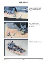
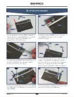
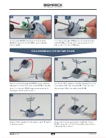
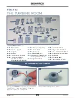
. ASSEMBLING THE TURBINE
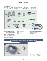
STAGE 92
THE TURBINE ROOM
92-02
92-03
92-05
92-06
92-08
92-09
J
K
L
G
92-19
92-15
C
D
F
92-01
92-04
A
B
92-07
92-10
H
I
92-11
92-12
92-13
92-14
92-16
92-17
92-18
M
N
O
F
G
F
G
E
E
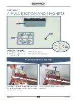
COMPONENTS CHECKLIST
92-01:
Floor section
92-02:
Turbine support
92-03:
Gangway
92-04
: Bolts x 4
92-05:
Transverse dividers x 8
92-06:
Transverse support
brackets (
A
) and a
longitudinal bulkhead (
B
)
92-07:
Turbine parts (
C
to
G
)
92-08:
Turbine head
92-09:
Turbine pipe
92-10:
Cable guides (
H
,
I
)
92-11:
Gangway (
J
), supports (
K
)
and angled brackets (
L
)
92-12:
Angled bulkhead
92-13:
Torpedo bulkhead
92-14:
Longitudinal bulkhead
92-15:
Front transverse bulkhead
92-16:
Rear transverse bulkhead
92-17:
Back wall
92-18:
Armoured deck
92-19:
Three railings (
M
to
O
)
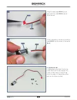
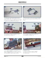
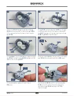
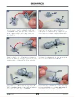
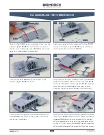
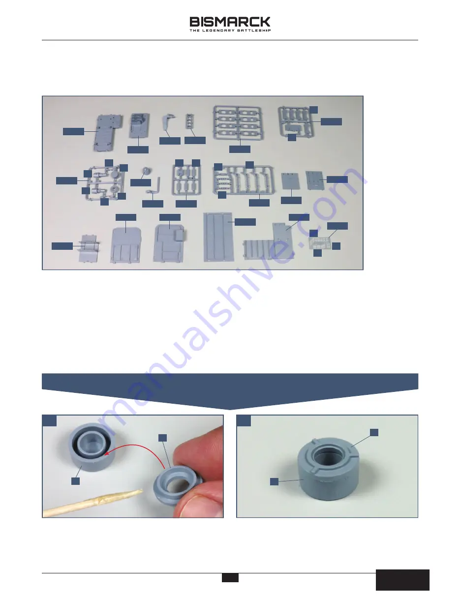
Take the frame
92-07
and separate the turbine parts
F
and
G
from it. Check how the parts fit together
Apply some glue to the rim of part
G
.
Glue parts
F
and
G
together as shown.
48
48
AGORA
MODELS
PB
AGORA
MODELS


