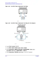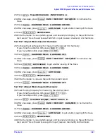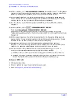
Chapter 2
2-89
System Verification and Performance Tests
Agilent 8753ET System Verification and Performance Tests
3. While the equipment is warming up, review the connector care information in
. Good connections and clean, undamaged connectors are critical for
accurate measurement results.
4. Insert the verification kit disk into the analyzer disk drive.
5. Press
.
6. If you want a printout of the verification data for all the devices, press
. If you want a printout of the
graph from the display, press
.
NOTE
If you switch on the record function, you cannot switch it off during the
verification procedure.
7. Position the paper in the printer so that printing starts at the top of the page.
8. If you have difficulty with the printer:
• If the interface on your printer is GPIB, verify that the printer address is set to 1 (or
change the setting in the analyzer to match the printer).
• If the interface on your printer is serial or parallel, be sure that you selected the
printer port and the printer type correctly. Refer to the analyzer’s user’s guide for
more information on how to perform these tasks.
9. Press
.
10.When the analyzer displays
Sys Ver Init DONE
, the initialization procedure is
complete.
CAUTION
Do not press
or recall another instrument state. You must use the
instrument state that you loaded during the initialization procedure.
Enhanced Response Calibration
11.Press
.
12.Press
.
13.Press
.
14.Press .
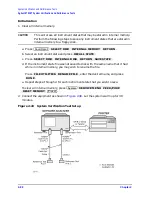
15.Connect the “open” end of the open/short combination (supplied in the HP/Agilent
85031B calibration kit) to reference test port 1, as shown in
Preset
Save/Recall
SELECT DISK INTERNAL DISK
System
SERVICE MENU TEST OPTIONS RECORD ON
DUMP GRAPH ON
System
SERVICE MENU TESTS SYS VER TESTS EXECUTE TEST
Preset
Cal
CAL KIT SELECT CAL KIT CAL KIT:7mm 85031 RETURN
RETURN
CALIBRATE MENU ENHANCED RESPONSE TRANS/REFL ENH.
ISOLATION OMIT ISOLATION
REFLECTION
Summary of Contents for 8753ES
Page 14: ...Contents xiv Contents ...
Page 15: ...1 1 1 Service Equipment and Analyzer Options ...
Page 26: ...1 12 Chapter1 Service Equipment and Analyzer Options Service and Support Options ...
Page 27: ...2 1 2 System Verification and Performance Tests ...
Page 203: ...3 1 3 Adjustments and Correction Constants ...
Page 262: ...3 60 Chapter3 Adjustments and Correction Constants Sequences for Mechanical Adjustments ...
Page 263: ...4 1 4 Start Troubleshooting Here ...
Page 297: ...5 1 5 Power Supply Troubleshooting ...
Page 317: ......
Page 318: ...6 1 6 Digital Control Troubleshooting ...
Page 337: ...6 20 Chapter6 Digital Control Troubleshooting GPIB Failures ...
Page 338: ...7 1 7 Source Troubleshooting ...
Page 369: ...7 32 Chapter7 Source Troubleshooting Source Group Troubleshooting Appendix ...
Page 370: ...8 1 8 Receiver Troubleshooting ...
Page 381: ...8 12 Chapter8 Receiver Troubleshooting Troubleshooting When One or More Inputs Look Good ...
Page 382: ...9 1 9 Accessories Troubleshooting ...
Page 389: ...9 8 Chapter9 Accessories Troubleshooting Inspect the Error Terms ...
Page 390: ...10 1 10 Service Key Menus and Error Messages ...
Page 439: ...10 50 Chapter10 Service Key Menus and Error Messages Error Messages ...
Page 440: ...11 1 11 Error Terms ...
Page 451: ...11 12 Chapter11 Error Terms Error Correction ...
Page 452: ...12 1 12 Theory of Operation ...
Page 482: ...13 1 13 Replaceable Parts ...
Page 487: ...13 6 Chapter13 Replaceable Parts Ordering Information Figure 13 1 Module Exchange Procedure ...
Page 500: ...Chapter 13 13 19 Replaceable Parts Replaceable Part Listings Figure 13 7 8753ET Cables Top ...
Page 502: ...Chapter 13 13 21 Replaceable Parts Replaceable Part Listings Figure 13 8 8753ES Cables Top ...
Page 512: ...Chapter 13 13 31 Replaceable Parts Replaceable Part Listings Figure 13 13 8753ES Cables Front ...
Page 544: ...14 1 14 Assembly Replacement and Post Repair Procedures ...
Page 550: ...Chapter 14 14 7 Assembly Replacement and Post Repair Procedures Covers Figure 14 2 Covers ...
Page 597: ...14 54 Chapter14 Assembly Replacement and Post Repair Procedures Post Repair Procedures ...


