


Chapter 1
1-7
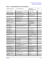
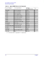
Service Equipment and Analyzer Options
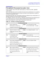
Principles of Microwave Connector Care
Principles of Microwave Connector Care
Proper connector care and connection techniques are critical for accurate, repeatable
measurements.
Refer to the calibration kit documentation for connector care information. Prior to making
connections to the network analyzer, carefully review the information about inspecting,
cleaning, and gaging connectors.
Having good connector care and connection techniques extends the life of these devices. In
addition, you obtain the most accurate measurements.
For additional connector care instruction, contact the nearest Agilent Technologies sales or
service office about course numbers HP/Agilent 24A and 24D.
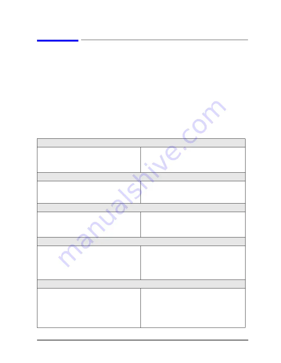
See the following table for quick reference tips about connector care.
Table 1-3
Connector Care Quick Reference
Handling and Storage
Do
Keep connectors clean
Do Not
Touch mating-plane surfaces
Extend sleeve or connector nut
Set connectors contact — end down
Use plastic end-caps during storage
Visual Inspection
Do
Inspect all connectors carefully
Do Not
Use a damaged connector — ever
Look for metal particles, scratches,
and dents
Connector Cleaning
Do
Try compressed air first
Do Not
Use any abrasives
Use isopropyl alcohol
Get liquid into plastic support beads
Clean connector threads
Gaging Connectors
Do
Clean and zero the gage before use
Do Not
Use an out-of-spec connector
Use the correct gage type
Use correct end of calibration block
Gage all connectors before first use
Making Connections
Do
Align connectors carefully
Do Not
Apply bending force to connection
Make preliminary connection lightly
Over tighten preliminary connection
Turn only the connector nut
Twist or screw any connection
Use a torque wrench for final
connect
Tighten past torque wrench “break”
point
Summary of Contents for 8753ES
Page 14: ...Contents xiv Contents ...
Page 15: ...1 1 1 Service Equipment and Analyzer Options ...
Page 26: ...1 12 Chapter1 Service Equipment and Analyzer Options Service and Support Options ...
Page 27: ...2 1 2 System Verification and Performance Tests ...
Page 203: ...3 1 3 Adjustments and Correction Constants ...
Page 262: ...3 60 Chapter3 Adjustments and Correction Constants Sequences for Mechanical Adjustments ...
Page 263: ...4 1 4 Start Troubleshooting Here ...
Page 297: ...5 1 5 Power Supply Troubleshooting ...
Page 317: ......
Page 318: ...6 1 6 Digital Control Troubleshooting ...
Page 337: ...6 20 Chapter6 Digital Control Troubleshooting GPIB Failures ...
Page 338: ...7 1 7 Source Troubleshooting ...
Page 369: ...7 32 Chapter7 Source Troubleshooting Source Group Troubleshooting Appendix ...
Page 370: ...8 1 8 Receiver Troubleshooting ...
Page 381: ...8 12 Chapter8 Receiver Troubleshooting Troubleshooting When One or More Inputs Look Good ...
Page 382: ...9 1 9 Accessories Troubleshooting ...
Page 389: ...9 8 Chapter9 Accessories Troubleshooting Inspect the Error Terms ...
Page 390: ...10 1 10 Service Key Menus and Error Messages ...
Page 439: ...10 50 Chapter10 Service Key Menus and Error Messages Error Messages ...
Page 440: ...11 1 11 Error Terms ...
Page 451: ...11 12 Chapter11 Error Terms Error Correction ...
Page 452: ...12 1 12 Theory of Operation ...
Page 482: ...13 1 13 Replaceable Parts ...
Page 487: ...13 6 Chapter13 Replaceable Parts Ordering Information Figure 13 1 Module Exchange Procedure ...
Page 500: ...Chapter 13 13 19 Replaceable Parts Replaceable Part Listings Figure 13 7 8753ET Cables Top ...
Page 502: ...Chapter 13 13 21 Replaceable Parts Replaceable Part Listings Figure 13 8 8753ES Cables Top ...
Page 512: ...Chapter 13 13 31 Replaceable Parts Replaceable Part Listings Figure 13 13 8753ES Cables Front ...
Page 544: ...14 1 14 Assembly Replacement and Post Repair Procedures ...
Page 550: ...Chapter 14 14 7 Assembly Replacement and Post Repair Procedures Covers Figure 14 2 Covers ...
Page 597: ...14 54 Chapter14 Assembly Replacement and Post Repair Procedures Post Repair Procedures ...