


5-8
Chapter 5
Power Supply Troubleshooting
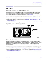
If the Red LED of the A15 Is ON
If the Red LED of the A15 Is ON
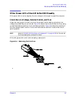
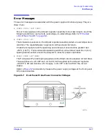
If the red LED is on or flashing, the power supply is shutting down. Use the following
procedures to determine which assembly is causing the problem.
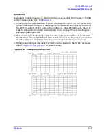
Check the A8 Post Regulator
1. Switch off the analyzer.
2. Disconnect the cable A15W1 from the A8 post regulator. (See
3. Switch on the analyzer and observe the red LED on A15.
• If the red LED goes out, the problem is probably the A8 post regulator. Continue to
“Verify the A15 Preregulator” on page 5-10
to first verify that the inputs to A8 are
correct.
• If the red LED is still on, fuse F4 in the preregulator A15 may need to be replaced if
the line voltage selector switch was set to 120 V, and the instrument was connected
to a 220 V supply.
• If the red LED is still on, the problem is probably the A15 preregulator, or one of the
assemblies obtaining power from it. Continue with
Summary of Contents for 8753ES
Page 14: ...Contents xiv Contents ...
Page 15: ...1 1 1 Service Equipment and Analyzer Options ...
Page 26: ...1 12 Chapter1 Service Equipment and Analyzer Options Service and Support Options ...
Page 27: ...2 1 2 System Verification and Performance Tests ...
Page 203: ...3 1 3 Adjustments and Correction Constants ...
Page 262: ...3 60 Chapter3 Adjustments and Correction Constants Sequences for Mechanical Adjustments ...
Page 263: ...4 1 4 Start Troubleshooting Here ...
Page 297: ...5 1 5 Power Supply Troubleshooting ...
Page 317: ......
Page 318: ...6 1 6 Digital Control Troubleshooting ...
Page 337: ...6 20 Chapter6 Digital Control Troubleshooting GPIB Failures ...
Page 338: ...7 1 7 Source Troubleshooting ...
Page 369: ...7 32 Chapter7 Source Troubleshooting Source Group Troubleshooting Appendix ...
Page 370: ...8 1 8 Receiver Troubleshooting ...
Page 381: ...8 12 Chapter8 Receiver Troubleshooting Troubleshooting When One or More Inputs Look Good ...
Page 382: ...9 1 9 Accessories Troubleshooting ...
Page 389: ...9 8 Chapter9 Accessories Troubleshooting Inspect the Error Terms ...
Page 390: ...10 1 10 Service Key Menus and Error Messages ...
Page 439: ...10 50 Chapter10 Service Key Menus and Error Messages Error Messages ...
Page 440: ...11 1 11 Error Terms ...
Page 451: ...11 12 Chapter11 Error Terms Error Correction ...
Page 452: ...12 1 12 Theory of Operation ...
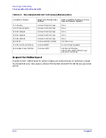
Page 482: ...13 1 13 Replaceable Parts ...
Page 487: ...13 6 Chapter13 Replaceable Parts Ordering Information Figure 13 1 Module Exchange Procedure ...
Page 500: ...Chapter 13 13 19 Replaceable Parts Replaceable Part Listings Figure 13 7 8753ET Cables Top ...
Page 502: ...Chapter 13 13 21 Replaceable Parts Replaceable Part Listings Figure 13 8 8753ES Cables Top ...
Page 512: ...Chapter 13 13 31 Replaceable Parts Replaceable Part Listings Figure 13 13 8753ES Cables Front ...
Page 544: ...14 1 14 Assembly Replacement and Post Repair Procedures ...
Page 550: ...Chapter 14 14 7 Assembly Replacement and Post Repair Procedures Covers Figure 14 2 Covers ...
Page 597: ...14 54 Chapter14 Assembly Replacement and Post Repair Procedures Post Repair Procedures ...


