


Chapter 2
2-47
System Verification and Performance Tests
Agilent 8753ES System Verification and Performance Tests
Crosstalk to Test Port 2 from 300 kHz to 3 GHz
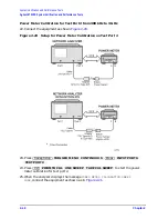
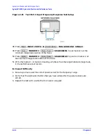
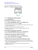
1. Connect the equipment as shown in
. Use the shorts from the calibration kit.
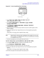
Figure 2-27
8753ES Crosstalk Measurement
2. Press
. Wait for the
sweeps to finish as indicated by the
Hld
indication on the left side of the display.
3. Press
.
4. Write the marker value (which appears on the display) in the performance test record.
Crosstalk to Test Port 1 from 300 kHz to 3 GHz
5. Press
.
6. Press
. Wait for the
sweeps to finish as indicated by the
Hld
indication on the left side of the display.
7. Press
.
8. Write the marker value (which appears on the analyzer display) in the performance test
record. This completes the test. If your analyzer has Option 006, proceed to the next
section.
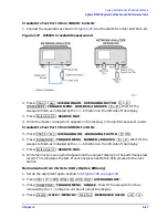
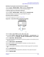
Normalization from 3 GHz to 6 GHz (Option 006 only)
1. Set up the equipment again as shown in
2. Press
.
3. Press
. Wait for the sweep to finish as
indicated by the
Hld
indication on the left side of the display.
4. Press
.
Chan 1
Avg
AVERAGING ON AVERAGING FACTOR
8
x1
Sweep Setup
TRIGGER MENU NUMBER of GROUPS
8
x1
Marker Search
SEARCH: MAX
Chan 2
Avg
AVERAGING ON AVERAGING FACTOR
8
x1
Sweep Setup
TRIGGER MENU NUMBER of GROUPS
8
x1
Marker Search
SEARCH: MAX
Start
3
G/n
Stop
6
G/n
Avg
AVERAGING OFF
Sweep Setup
TRIGGER MENU SINGLE
Display
DATA
→
MEMORY
Scale Ref
REFERENCE VALUE
−
90
x1
Summary of Contents for 8753ES
Page 14: ...Contents xiv Contents ...
Page 15: ...1 1 1 Service Equipment and Analyzer Options ...
Page 26: ...1 12 Chapter1 Service Equipment and Analyzer Options Service and Support Options ...
Page 27: ...2 1 2 System Verification and Performance Tests ...
Page 203: ...3 1 3 Adjustments and Correction Constants ...
Page 262: ...3 60 Chapter3 Adjustments and Correction Constants Sequences for Mechanical Adjustments ...
Page 263: ...4 1 4 Start Troubleshooting Here ...
Page 297: ...5 1 5 Power Supply Troubleshooting ...
Page 317: ......
Page 318: ...6 1 6 Digital Control Troubleshooting ...
Page 337: ...6 20 Chapter6 Digital Control Troubleshooting GPIB Failures ...
Page 338: ...7 1 7 Source Troubleshooting ...
Page 369: ...7 32 Chapter7 Source Troubleshooting Source Group Troubleshooting Appendix ...
Page 370: ...8 1 8 Receiver Troubleshooting ...
Page 381: ...8 12 Chapter8 Receiver Troubleshooting Troubleshooting When One or More Inputs Look Good ...
Page 382: ...9 1 9 Accessories Troubleshooting ...
Page 389: ...9 8 Chapter9 Accessories Troubleshooting Inspect the Error Terms ...
Page 390: ...10 1 10 Service Key Menus and Error Messages ...
Page 439: ...10 50 Chapter10 Service Key Menus and Error Messages Error Messages ...
Page 440: ...11 1 11 Error Terms ...
Page 451: ...11 12 Chapter11 Error Terms Error Correction ...
Page 452: ...12 1 12 Theory of Operation ...
Page 482: ...13 1 13 Replaceable Parts ...
Page 487: ...13 6 Chapter13 Replaceable Parts Ordering Information Figure 13 1 Module Exchange Procedure ...
Page 500: ...Chapter 13 13 19 Replaceable Parts Replaceable Part Listings Figure 13 7 8753ET Cables Top ...
Page 502: ...Chapter 13 13 21 Replaceable Parts Replaceable Part Listings Figure 13 8 8753ES Cables Top ...
Page 512: ...Chapter 13 13 31 Replaceable Parts Replaceable Part Listings Figure 13 13 8753ES Cables Front ...
Page 544: ...14 1 14 Assembly Replacement and Post Repair Procedures ...
Page 550: ...Chapter 14 14 7 Assembly Replacement and Post Repair Procedures Covers Figure 14 2 Covers ...
Page 597: ...14 54 Chapter14 Assembly Replacement and Post Repair Procedures Post Repair Procedures ...


