


2-48
Chapter 2
System Verification and Performance Tests
Agilent 8753ES System Verification and Performance Tests
5. Press
.
6. Press
. Wait for the sweep to finish as
indicated by the
Hld
indication on the left side of the display.
7. Press
.
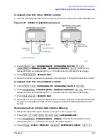
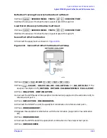
Crosstalk to Test Port 2 from 3 GHz to 6 GHz (Option 006 only)
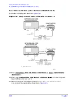
8. Connect the equipment as shown in
. Press
.
9. Press
. Wait for the
sweeps to finish as indicated by the
Hld
notation on the left side of the display.
10.Press .
11.Write the marker value (which appears on the analyzer display) in the performance test
record.
Crosstalk to Test Port 1 from 3 GHz to 6 GHz (Option 006 only)
12.Press
.
13.Press
. Wait for the
sweeps to finish as indicated by the
Hld
notation on the left side of the display.
14.Press .
15.Write the marker value (which appears on the analyzer display) in the performance test
record.
In Case of Difficulty
1. Remove the instrument top cover. Using an 8 lb-inch torque wrench, verify that all
semirigid cables connected to the sampler/mixer assemblies are tight. In addition,
tighten any loose screws on the sampler/mixer assemblies (A4/5/6) and the pulse
generator assembly (A7).
2. Remove the instrument bottom cover. Refer to
. Verify that cables W1, W31
and W32 are tight.
3. Repeat this test.
Chan 1
Avg
AVERAGING OFF
Sweep Setup
TRIGGER MENU SINGLE
Display
DATA
→
MEMORY
Scale Ref
REFERENCE VALUE
−
90
x1
Avg
AVERAGING ON
Sweep Setup
TRIGGER MENU NUMBER of GROUPS
8
x1
Marker Search
SEARCH: MAX
Chan 2
Avg
AVERAGING ON
Sweep Setup
TRIGGER MENU NUMBER of GROUPS
8
x1
Marker Search
SEARCH: MAX
Summary of Contents for 8753ES
Page 14: ...Contents xiv Contents ...
Page 15: ...1 1 1 Service Equipment and Analyzer Options ...
Page 26: ...1 12 Chapter1 Service Equipment and Analyzer Options Service and Support Options ...
Page 27: ...2 1 2 System Verification and Performance Tests ...
Page 203: ...3 1 3 Adjustments and Correction Constants ...
Page 262: ...3 60 Chapter3 Adjustments and Correction Constants Sequences for Mechanical Adjustments ...
Page 263: ...4 1 4 Start Troubleshooting Here ...
Page 297: ...5 1 5 Power Supply Troubleshooting ...
Page 317: ......
Page 318: ...6 1 6 Digital Control Troubleshooting ...
Page 337: ...6 20 Chapter6 Digital Control Troubleshooting GPIB Failures ...
Page 338: ...7 1 7 Source Troubleshooting ...
Page 369: ...7 32 Chapter7 Source Troubleshooting Source Group Troubleshooting Appendix ...
Page 370: ...8 1 8 Receiver Troubleshooting ...
Page 381: ...8 12 Chapter8 Receiver Troubleshooting Troubleshooting When One or More Inputs Look Good ...
Page 382: ...9 1 9 Accessories Troubleshooting ...
Page 389: ...9 8 Chapter9 Accessories Troubleshooting Inspect the Error Terms ...
Page 390: ...10 1 10 Service Key Menus and Error Messages ...
Page 439: ...10 50 Chapter10 Service Key Menus and Error Messages Error Messages ...
Page 440: ...11 1 11 Error Terms ...
Page 451: ...11 12 Chapter11 Error Terms Error Correction ...
Page 452: ...12 1 12 Theory of Operation ...
Page 482: ...13 1 13 Replaceable Parts ...
Page 487: ...13 6 Chapter13 Replaceable Parts Ordering Information Figure 13 1 Module Exchange Procedure ...
Page 500: ...Chapter 13 13 19 Replaceable Parts Replaceable Part Listings Figure 13 7 8753ET Cables Top ...
Page 502: ...Chapter 13 13 21 Replaceable Parts Replaceable Part Listings Figure 13 8 8753ES Cables Top ...
Page 512: ...Chapter 13 13 31 Replaceable Parts Replaceable Part Listings Figure 13 13 8753ES Cables Front ...
Page 544: ...14 1 14 Assembly Replacement and Post Repair Procedures ...
Page 550: ...Chapter 14 14 7 Assembly Replacement and Post Repair Procedures Covers Figure 14 2 Covers ...
Page 597: ...14 54 Chapter14 Assembly Replacement and Post Repair Procedures Post Repair Procedures ...


