


Chapter 9
9-5
Accessories Troubleshooting
Inspect the Error Terms
Inspect the Error Terms
Error terms are a measure of a “system”: a network analyzer, calibration kit, and any
cables used. As required, refer to
for the following:
• The specific measurement calibration procedure used to generate the error terms.
• The routines required to extract error terms from the instrument.
• Typical error term data.
Use
to cross-reference error term data to system faults.
If you detect problems using error term analysis, use the following approach to isolate the
fault:
1. Check the cable by examining the load match and transmission tracking terms. If those
2. Verify the calibration kit devices:
• Loads (for 8753ES): If the directivity error term looks good, the load and the test port
are good. If directivity looks bad, connect the same load on the other test port and
measure its directivity. If the second port looks bad, as if the problem had shifted
with the load, replace the load. If the second port looks good, as if the load had not
been the problem, troubleshoot the first port.
• Loads (for 8753ET): If the directivity error term looks good, the load and the test port
are good. If directivity looks bad, connect a known good load to the Reflection port
and measure its directivity. If the directivity now looks good, replace the original
load. If the directivity still looks bad, troubleshoot the Reflection port.
• Shorts and opens: If the source match and reflection tracking terms look good, the
shorts and the opens are good. If these terms look bad while the rest of the terms
look good, proceed to
“Verify Shorts and Opens” on page 9-6
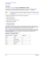
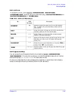
Table 9-1
Components Related to Specific Error Terms
Component Directivity
Source
Match
Reflection
Tracking
Isolation Load
Match
Transmission
Tracking
Calibration Kit
load
X
open/short
X
X
Analyzer
sampler
X
X
X
A10 digital IF
X
test port connectors
X
X
X
X
X
X
External cables
X
X
Summary of Contents for 8753ES
Page 14: ...Contents xiv Contents ...
Page 15: ...1 1 1 Service Equipment and Analyzer Options ...
Page 26: ...1 12 Chapter1 Service Equipment and Analyzer Options Service and Support Options ...
Page 27: ...2 1 2 System Verification and Performance Tests ...
Page 203: ...3 1 3 Adjustments and Correction Constants ...
Page 262: ...3 60 Chapter3 Adjustments and Correction Constants Sequences for Mechanical Adjustments ...
Page 263: ...4 1 4 Start Troubleshooting Here ...
Page 297: ...5 1 5 Power Supply Troubleshooting ...
Page 317: ......
Page 318: ...6 1 6 Digital Control Troubleshooting ...
Page 337: ...6 20 Chapter6 Digital Control Troubleshooting GPIB Failures ...
Page 338: ...7 1 7 Source Troubleshooting ...
Page 369: ...7 32 Chapter7 Source Troubleshooting Source Group Troubleshooting Appendix ...
Page 370: ...8 1 8 Receiver Troubleshooting ...
Page 381: ...8 12 Chapter8 Receiver Troubleshooting Troubleshooting When One or More Inputs Look Good ...
Page 382: ...9 1 9 Accessories Troubleshooting ...
Page 389: ...9 8 Chapter9 Accessories Troubleshooting Inspect the Error Terms ...
Page 390: ...10 1 10 Service Key Menus and Error Messages ...
Page 439: ...10 50 Chapter10 Service Key Menus and Error Messages Error Messages ...
Page 440: ...11 1 11 Error Terms ...
Page 451: ...11 12 Chapter11 Error Terms Error Correction ...
Page 452: ...12 1 12 Theory of Operation ...
Page 482: ...13 1 13 Replaceable Parts ...
Page 487: ...13 6 Chapter13 Replaceable Parts Ordering Information Figure 13 1 Module Exchange Procedure ...
Page 500: ...Chapter 13 13 19 Replaceable Parts Replaceable Part Listings Figure 13 7 8753ET Cables Top ...
Page 502: ...Chapter 13 13 21 Replaceable Parts Replaceable Part Listings Figure 13 8 8753ES Cables Top ...
Page 512: ...Chapter 13 13 31 Replaceable Parts Replaceable Part Listings Figure 13 13 8753ES Cables Front ...
Page 544: ...14 1 14 Assembly Replacement and Post Repair Procedures ...
Page 550: ...Chapter 14 14 7 Assembly Replacement and Post Repair Procedures Covers Figure 14 2 Covers ...
Page 597: ...14 54 Chapter14 Assembly Replacement and Post Repair Procedures Post Repair Procedures ...


