


Chapter 2
2-131
System Verification and Performance Tests
Agilent 8753ET System Verification and Performance Tests
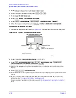
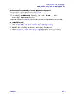
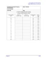
10. Uncorrected Port Performance
The analyzer can perform error-correction and store the error coefficients. These error
coefficients are, in fact, measurements of the analyzer’s uncorrected port performance.
NOTE
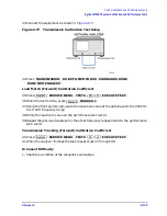
The crosstalk error terms are omitted in this procedure. They are covered in
the “Test Port Crosstalk” performance test.
Analyzer warm-up time: 30 minutes
Specifications
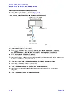
Required Equipment
Uncorrected
a
Error Terms
a. At 25
°
C
±
5
°
C, with less than 1
°
C deviation from the measurement calibration
temperature.
Frequency Range
300 kHz to 1.3 GHz
1.3 GHz to 3 GHz
3 GHz to 6 GHz
b
b. Only for analyzers with Option 006.
Directivity
30 dB
24 dB
19 dB
Source Match
(Standard)
25 dB
20 dB
14 dB
Source Match
(Option 004)
23 dB
18 dB
14 dB
Load Match (raw)
24 dB
19 dB
16 dB
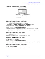
Reflection Tracking
±
1.0 dB
±
1.0 dB
±
2.0 dB
Transmission
Tracking
±
1.5 dB
±
1.5 dB
±
2.5 dB
Description
HP/Agilent Part or Model Number
Calibration Kit: 50
Ω
, Type-N
85032B
Cable: Type-N, 24-inch
8120-4781
Summary of Contents for 8753ES
Page 14: ...Contents xiv Contents ...
Page 15: ...1 1 1 Service Equipment and Analyzer Options ...
Page 26: ...1 12 Chapter1 Service Equipment and Analyzer Options Service and Support Options ...
Page 27: ...2 1 2 System Verification and Performance Tests ...
Page 203: ...3 1 3 Adjustments and Correction Constants ...
Page 262: ...3 60 Chapter3 Adjustments and Correction Constants Sequences for Mechanical Adjustments ...
Page 263: ...4 1 4 Start Troubleshooting Here ...
Page 297: ...5 1 5 Power Supply Troubleshooting ...
Page 317: ......
Page 318: ...6 1 6 Digital Control Troubleshooting ...
Page 337: ...6 20 Chapter6 Digital Control Troubleshooting GPIB Failures ...
Page 338: ...7 1 7 Source Troubleshooting ...
Page 369: ...7 32 Chapter7 Source Troubleshooting Source Group Troubleshooting Appendix ...
Page 370: ...8 1 8 Receiver Troubleshooting ...
Page 381: ...8 12 Chapter8 Receiver Troubleshooting Troubleshooting When One or More Inputs Look Good ...
Page 382: ...9 1 9 Accessories Troubleshooting ...
Page 389: ...9 8 Chapter9 Accessories Troubleshooting Inspect the Error Terms ...
Page 390: ...10 1 10 Service Key Menus and Error Messages ...
Page 439: ...10 50 Chapter10 Service Key Menus and Error Messages Error Messages ...
Page 440: ...11 1 11 Error Terms ...
Page 451: ...11 12 Chapter11 Error Terms Error Correction ...
Page 452: ...12 1 12 Theory of Operation ...
Page 482: ...13 1 13 Replaceable Parts ...
Page 487: ...13 6 Chapter13 Replaceable Parts Ordering Information Figure 13 1 Module Exchange Procedure ...
Page 500: ...Chapter 13 13 19 Replaceable Parts Replaceable Part Listings Figure 13 7 8753ET Cables Top ...
Page 502: ...Chapter 13 13 21 Replaceable Parts Replaceable Part Listings Figure 13 8 8753ES Cables Top ...
Page 512: ...Chapter 13 13 31 Replaceable Parts Replaceable Part Listings Figure 13 13 8753ES Cables Front ...
Page 544: ...14 1 14 Assembly Replacement and Post Repair Procedures ...
Page 550: ...Chapter 14 14 7 Assembly Replacement and Post Repair Procedures Covers Figure 14 2 Covers ...
Page 597: ...14 54 Chapter14 Assembly Replacement and Post Repair Procedures Post Repair Procedures ...


