


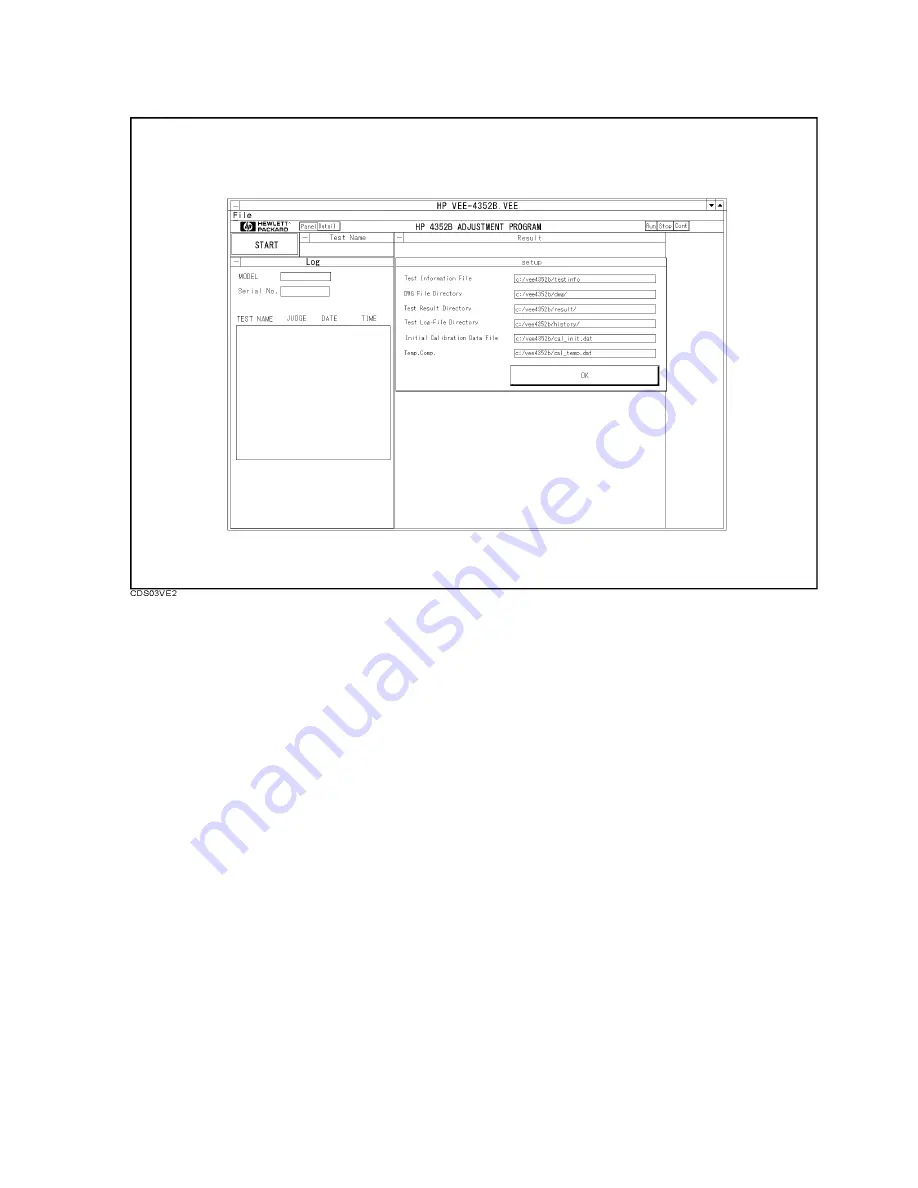
Figure
3-3.
Setup
Menu
12.
The
Calibration
F
actor
Entry
Menu
for
an
8482A
will
be
displayed.
Edit
the
reference
calibration
factor
and
the
calibration
factor
to
match
your
power
sensor
.
Then
click
on
OK.
13.
The
Serial
Number
Entry
Menu
will
be
displayed.
Enter
the
serial
number
,
and
click
on
If
OK,
Push
here!
.
14.
The
list
Box
Menu
will
be
displayed
as
shown
in
Figure
3-4.
Choose
the
adjustment
items
using
the
mouse
.
Click
on
OK
to
start
the
adjustment
procedures
.
If
you
click
on
Select
All,
you
can
easily
activate
all
adjustment
items
.
These
selected
adjustments
are
performed
in
the
listed
order
.
3-6
Adjustments
and
Correction
Constants
Summary of Contents for 4352B
Page 11: ......
Page 31: ......
Page 73: ......
Page 80: ...Figure 3 4 List Box Menu Adjustments and Correction Constants 3 7 ...
Page 82: ...Figure 3 6 Reference Frequency Adjustment Location Adjustments and Correction Constants 3 9 ...
Page 85: ...Figure 3 9 Third IF AMP GAIN Adjustment Location 3 12 Adjustments and Correction Constants ...
Page 103: ...Figure 4 1 Troubleshooting Organization 4 2 Overall T roubleshooting ...
Page 113: ......
Page 130: ...Figure 5 11 Power Supply Block Diagram 1 Power Supply T roubleshooting 5 17 ...
Page 131: ...Figure 5 12 Power Supply Block Diagram 2 5 18 Power Supply T roubleshooting ...
Page 132: ...Figure 5 13 Power Supply Block Diagram 3 Power Supply T roubleshooting 5 19 ...
Page 133: ......
Page 135: ...Figure 6 1 Digital Control Group Simpli ed Block Diagram 6 2 Digital Control T roubleshooting ...
Page 146: ...Figure 7 2 Source Group Troubleshooting Flow Source Group T roubleshooting 7 3 ...
Page 154: ...Figure 8 2 Receiver Group Troubleshooting Flow Receiver Group T roubleshooting 8 3 ...
Page 198: ...Figure 10 1 Power Supply Functional Group Simpli ed Block Diagram Theory of Operation 10 3 ...
Page 203: ...Figure 10 3 Digital Control Group Simpli ed Block Diagram 10 8 Theory of Operation ...
Page 269: ......
Page 272: ...Figure B 1 Power Cable Supplied Power Requirement B 3 ...
Page 273: ......


