


57
Chapter 3: Testing Logic Analyzer Performance
Test Pod 2 in 500 Mb/s Mode
Yes
to erase the data and continue.
25
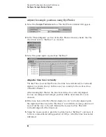
Perform the procedure “Determine PASS/FAIL (1 of 2 tests)” on page 47.
26
Select the Run Repetitive icon
.
27
Perform the procedure “Determine PASS/FAIL (2 of 2 tests)” on page 49.
Test the complement of the bits (Pod 1, 500 Mb/s mode)
Now test the logic analyzer using complement data.
1
On the 8133A pulse generator, in the PULSE setup for CHANNEL 2, select
COMP.
2
Note that the signal on the oscilloscope has moved. Change the
oscilloscope’s horizontal position to -725 ps (or as required) to center the
measured pulse on the oscilloscope display.
3
Verify the DC offset and adjust it if necessary. See page 36.
4
Deskew the oscilloscope if necessary. See page 37.
5
Verify that the pulse width is set to 1.5 ns. See page 39.
6
Run Eye Finder and align stray channels if necessary.
7
Perform the procedure “Determine PASS/FAIL (1 of 2 tests)” on page 47.
8
Select the Run Repetitive icon
.
9
Perform the procedure “Determine PASS/FAIL (2 of 2 tests)” on page 49
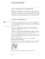
Test Pod 2 in 500 Mb/s Mode
1
Leave the first E5383A Flying Lead Probe Set connected to Pod 1 of the
logic analyzer. Remove the Pod 1 flying leads 2, 6, 10, and 14 from the
SMA/Flying Lead test connectors. Do not remove the flying leads that are
connected to CLK and CLK flying leads.
2
Connect the second E5383A Flying Lead Probe Set to Pod 2.
3
Connect the Pod 2 E5383A Flying Lead Probe Set’s bits 6 and 14 to the
Summary of Contents for 16900 Series
Page 3: ...3 Chapter The 16910A Logic Analyzer The 16911A Logic Analyzer...
Page 8: ...8 Contents...
Page 14: ...14 Chapter 1 General Information...
Page 18: ...18 Chapter 2 Preparing for Use...
Page 61: ...61 4 Calibrating This chapter gives you instructions for calibrating the logic analyzer...
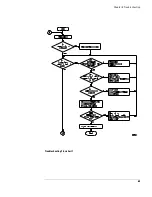
Page 65: ...65 Chapter 5 Troubleshooting Troubleshooting Flowchart 1...
Page 66: ...66 Chapter 5 Troubleshooting Troubleshooting Flowchart 2...
Page 82: ...82 Chapter 5 Troubleshooting To test the cables 18 Return to the troubleshooting flow chart...
Page 94: ...94 Chapter 7 Replaceable Parts 16910A Exploded View Exploded view of the 16910A logic analyzer...
Page 95: ...95 Chapter 7 Replaceable Parts 16911A Exploded View Exploded view of the 16911A logic analyzer...
Page 96: ...96 Chapter 7 Replaceable Parts...
Page 102: ...102 Index...


