


56
Chapter 3: Testing Logic Analyzer Performance
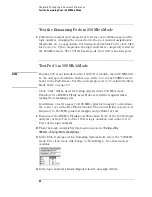
Test Pod 1 in 500 Mb/s Mode
18
Now set the pulse generator to the new test frequency. The logic analyzer
will be tested using a double-edge clock. The test frequency is half the test
clock rate because data is acquired on both the rising edge and the falling
edge of the clock. Set the frequency to 250 MHz plus the frequency
uncertainty of the pulse generator, plus a test margin of 1%.
For example, if you are using an 8133A pulse generator, the frequency
accuracy is ±1% of setting. Use a test margin of 1%. Set the frequency to
250 MHz plus 2% (255 MHz).
19
The pulse measured on the oscilloscope may have moved slightly. Verify
the DC offset and adjust it if necessary. See page 36.
20
Verify the oscilloscope Deskew and adjust if necessary. See page 37.
21
Adjust the measured pulse width from the pulse generator to 1.5 ns
(minus the test margin) as described on page 39.
22
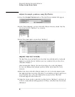
Open the Eye Finder window, and align the blue bars vertically. See page
44.
23
Grab the blue bar for “My Bus 1” and move it to the recommended starting
position you noted on page 55.
24
Run Eye Finder again. Some eyes may close, but the eyes in the sampling
position you chose on page 55 should remain open.
When you close the Analyzer Setup window a dialog may appear. If so, answer
Summary of Contents for 16900 Series
Page 3: ...3 Chapter The 16910A Logic Analyzer The 16911A Logic Analyzer...
Page 8: ...8 Contents...
Page 14: ...14 Chapter 1 General Information...
Page 18: ...18 Chapter 2 Preparing for Use...
Page 61: ...61 4 Calibrating This chapter gives you instructions for calibrating the logic analyzer...
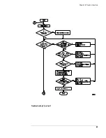
Page 65: ...65 Chapter 5 Troubleshooting Troubleshooting Flowchart 1...
Page 66: ...66 Chapter 5 Troubleshooting Troubleshooting Flowchart 2...
Page 82: ...82 Chapter 5 Troubleshooting To test the cables 18 Return to the troubleshooting flow chart...
Page 94: ...94 Chapter 7 Replaceable Parts 16910A Exploded View Exploded view of the 16910A logic analyzer...
Page 95: ...95 Chapter 7 Replaceable Parts 16911A Exploded View Exploded view of the 16911A logic analyzer...
Page 96: ...96 Chapter 7 Replaceable Parts...
Page 102: ...102 Index...


