


50
Chapter 3: Testing Logic Analyzer Performance
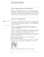
Test Pod 1 in 250 Mb/s Mode
NOTE:
As a point of curiosity, you may want to determine the absolute minimum
pulse width and/or absolute maximum frequency at which data can be
acquired. The “Performance Test Record” on page 60 does not include
places for recording these values because the Performance Verification
procedure only verifies that the logic analyzer meets specifications.
Determination of additional parameters is not required, but may be
performed at the discretion of the calibration laboratory.
On some pulse generators, the signal outputs may become unstable for a
short period of time when the signal parameters are adjusted. Adjusting
the pulse generator while the logic analyzer is running can cause a false
failure.
If the error message is displayed immediately after making an adjustment
to the pulse generator, select OK to close the error display window and re-
run the logic analyzer.
Test the complement of the bits (250 Mb/s mode)
Now test the logic analyzer using complement data.
1
On the 8133A pulse generator, in the PULSE setup for CHANNEL 2, select
COMP.
2
Note that the signal on the oscilloscope has moved. Change the
oscilloscope’s horizontal position to -725 ps (or as required) to center the
measured pulse on the oscilloscope display.
3
Verify the DC offset and adjust it if necessary. See page 36.
4
Deskew the oscilloscope if necessary. See page 37.
5
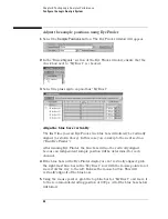
Adjust the oscilloscope’s measurement markers to measure the pulse
width. Set the markers so that
∆
=1.43 ns (this assumes you are using the
8133A pulse generator and the Infiniium 54845A oscilloscope). Adjust the
pulse generator so that the pulse width is 1.43 ns as measured by the
Summary of Contents for 16900 Series
Page 3: ...3 Chapter The 16910A Logic Analyzer The 16911A Logic Analyzer...
Page 8: ...8 Contents...
Page 14: ...14 Chapter 1 General Information...
Page 18: ...18 Chapter 2 Preparing for Use...
Page 61: ...61 4 Calibrating This chapter gives you instructions for calibrating the logic analyzer...
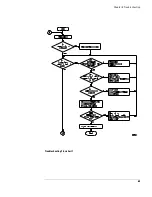
Page 65: ...65 Chapter 5 Troubleshooting Troubleshooting Flowchart 1...
Page 66: ...66 Chapter 5 Troubleshooting Troubleshooting Flowchart 2...
Page 82: ...82 Chapter 5 Troubleshooting To test the cables 18 Return to the troubleshooting flow chart...
Page 94: ...94 Chapter 7 Replaceable Parts 16910A Exploded View Exploded view of the 16910A logic analyzer...
Page 95: ...95 Chapter 7 Replaceable Parts 16911A Exploded View Exploded view of the 16911A logic analyzer...
Page 96: ...96 Chapter 7 Replaceable Parts...
Page 102: ...102 Index...


