


35
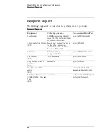
Chapter 3: Testing Logic Analyzer Performance
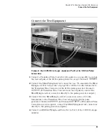
Connect the Test Equipment
7
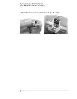
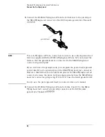
Connect the E5383A Flying Lead Probe Set’s bits 6 and 14 to the SMA/
Flying Lead test connector’s pin strip connector at the 8133A pulse
generator’s Channel 2 OUTPUT.
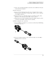
Connect the 8133A Pulse Generator Output to the 54845A
Oscilloscope
8
Attach Male BNC to Female SMA adapters to Channels 1 and 2 on the
54845A oscilloscope.
9
Attach one end of an SMA cable to the Male BNC to Female SMA adapter
on Channel 1 of the oscilloscope.
10
Attach the other end of the SMA cable to the SMA/Flying Lead connector
at the Channel 2 OUTPUT of the 8133A pulse generator.
11
Attach one end of the other SMA cable to the Male BNC to Female SMA
adapter on Channel 2 of the oscilloscope.
12
Attach the other end of the SMA cable to the SMA/Flying Lead connector
at the Channel 2 OUTPUT of the 8133A pulse generator.
Summary of Contents for 16900 Series
Page 3: ...3 Chapter The 16910A Logic Analyzer The 16911A Logic Analyzer...
Page 8: ...8 Contents...
Page 14: ...14 Chapter 1 General Information...
Page 18: ...18 Chapter 2 Preparing for Use...
Page 61: ...61 4 Calibrating This chapter gives you instructions for calibrating the logic analyzer...
Page 65: ...65 Chapter 5 Troubleshooting Troubleshooting Flowchart 1...
Page 66: ...66 Chapter 5 Troubleshooting Troubleshooting Flowchart 2...
Page 82: ...82 Chapter 5 Troubleshooting To test the cables 18 Return to the troubleshooting flow chart...
Page 94: ...94 Chapter 7 Replaceable Parts 16910A Exploded View Exploded view of the 16910A logic analyzer...
Page 95: ...95 Chapter 7 Replaceable Parts 16911A Exploded View Exploded view of the 16911A logic analyzer...
Page 96: ...96 Chapter 7 Replaceable Parts...
Page 102: ...102 Index...


