


25
Chapter 3: Testing Logic Analyzer Performance
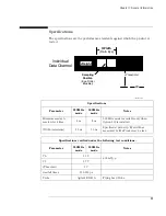
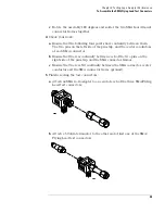
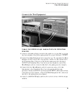
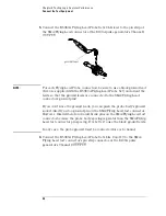
To Assemble the SMA/Flying Lead Test Connectors
c
Rotate the assembly 180 degrees and solder the two SMA board mount
connector frames together.
4
Check your work:
a
Ensure that the following four points have continuity between them:
The two pins on the left side of the pin strip, and the center conductors
of each SMA connector.
b
Ensure that there is continuity between each of the two pins on the
right side of the pin strip, and the SMA connector frames.
c
Ensure that there is NO continuity between the SMA connector center
conductor and the SMA connector frame (ground).
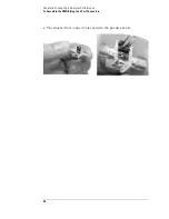
5
Finish creating the test connectors:
a
Attach an SMA m-m adapter to one end of each of the three SMA/Flying
Lead test connectors.
b
Attach a 50 ohm terminator to the other end of just one of the SMA/
Flying Lead test connectors.
Summary of Contents for 16900 Series
Page 3: ...3 Chapter The 16910A Logic Analyzer The 16911A Logic Analyzer...
Page 8: ...8 Contents...
Page 14: ...14 Chapter 1 General Information...
Page 18: ...18 Chapter 2 Preparing for Use...
Page 61: ...61 4 Calibrating This chapter gives you instructions for calibrating the logic analyzer...
Page 65: ...65 Chapter 5 Troubleshooting Troubleshooting Flowchart 1...
Page 66: ...66 Chapter 5 Troubleshooting Troubleshooting Flowchart 2...
Page 82: ...82 Chapter 5 Troubleshooting To test the cables 18 Return to the troubleshooting flow chart...
Page 94: ...94 Chapter 7 Replaceable Parts 16910A Exploded View Exploded view of the 16910A logic analyzer...
Page 95: ...95 Chapter 7 Replaceable Parts 16911A Exploded View Exploded view of the 16911A logic analyzer...
Page 96: ...96 Chapter 7 Replaceable Parts...
Page 102: ...102 Index...


