


24
Chapter 3: Testing Logic Analyzer Performance
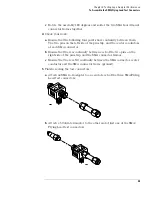
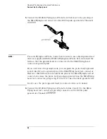
To Assemble the SMA/Flying Lead Test Connectors
2
Solder the pin strip to the SMA board mount connector:
a
Solder the leads on the left side of the pin strip to the center conductor
of the SMA connector as shown in the diagram below.
b
Solder the leads on the right side of the pin strip to the inside of the
SMA connector’s frame as shown in the diagram below. Use a small
amount of solder.
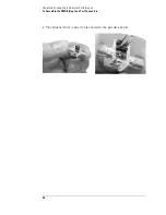
3
Attach the second SMA board mount connector:
a
Re-heat the solder connection made in the previous step, and attach
the second SMA connector, as shown in the diagram below. Note that
the second SMA connector is upside-down, compared to the first. Add a
little solder to make a good connection.
b
Solder the center conductor of the second SMA connector to the center
conductor of the first SMA connector and the leads on the left side of
the pin strip.
solder
Summary of Contents for 16900 Series
Page 3: ...3 Chapter The 16910A Logic Analyzer The 16911A Logic Analyzer...
Page 8: ...8 Contents...
Page 14: ...14 Chapter 1 General Information...
Page 18: ...18 Chapter 2 Preparing for Use...
Page 61: ...61 4 Calibrating This chapter gives you instructions for calibrating the logic analyzer...
Page 65: ...65 Chapter 5 Troubleshooting Troubleshooting Flowchart 1...
Page 66: ...66 Chapter 5 Troubleshooting Troubleshooting Flowchart 2...
Page 82: ...82 Chapter 5 Troubleshooting To test the cables 18 Return to the troubleshooting flow chart...
Page 94: ...94 Chapter 7 Replaceable Parts 16910A Exploded View Exploded view of the 16910A logic analyzer...
Page 95: ...95 Chapter 7 Replaceable Parts 16911A Exploded View Exploded view of the 16911A logic analyzer...
Page 96: ...96 Chapter 7 Replaceable Parts...
Page 102: ...102 Index...


